Key Supply Chain Performance Metrics to Evaluate Reliability
Why do supply chains fail despite extensive planning? Why do suppliers miss deadlines even with strict...
Where to Order CNC Machining Industrial Applications – Best B2B Solutions
Industries like automotive, aerospace, and electronics often face challenges when sourcing reliable CNC...
How Welding Cables Ensure Power and Safety in High-Temperature Operations
High-temperature environments in aerospace, automotive, and heavy manufacturing introduce complex challenges....
Why Custom Aluminum Extrusions Are the Future of Sustainable Construction Materials
Sustainable construction has become a core pillar of modern infrastructure development. Global construction...
Durability Requirements in Alloy Steel Machining for Construction Equipment
Construction equipment works harder than most industrial machines. Excavators strike rock repeatedly....
How to Select Industrial Cartridge Heaters for Maximum Performance and Longevity
Precision thermal management drives efficiency in high-temperature industrial processes. Industrial Cartridge...
Explore Your New Product Development with Frigate
Congratulations! You’ve conceptualized a brilliant idea for a new product. It can disrupt the market,...
Benchmarking Cosmetic Finish Quality in Sheet Metal Parts for Premium Consumer Products
Premium consumer products compete heavily on visual precision, tactile experience, and perceived quality....
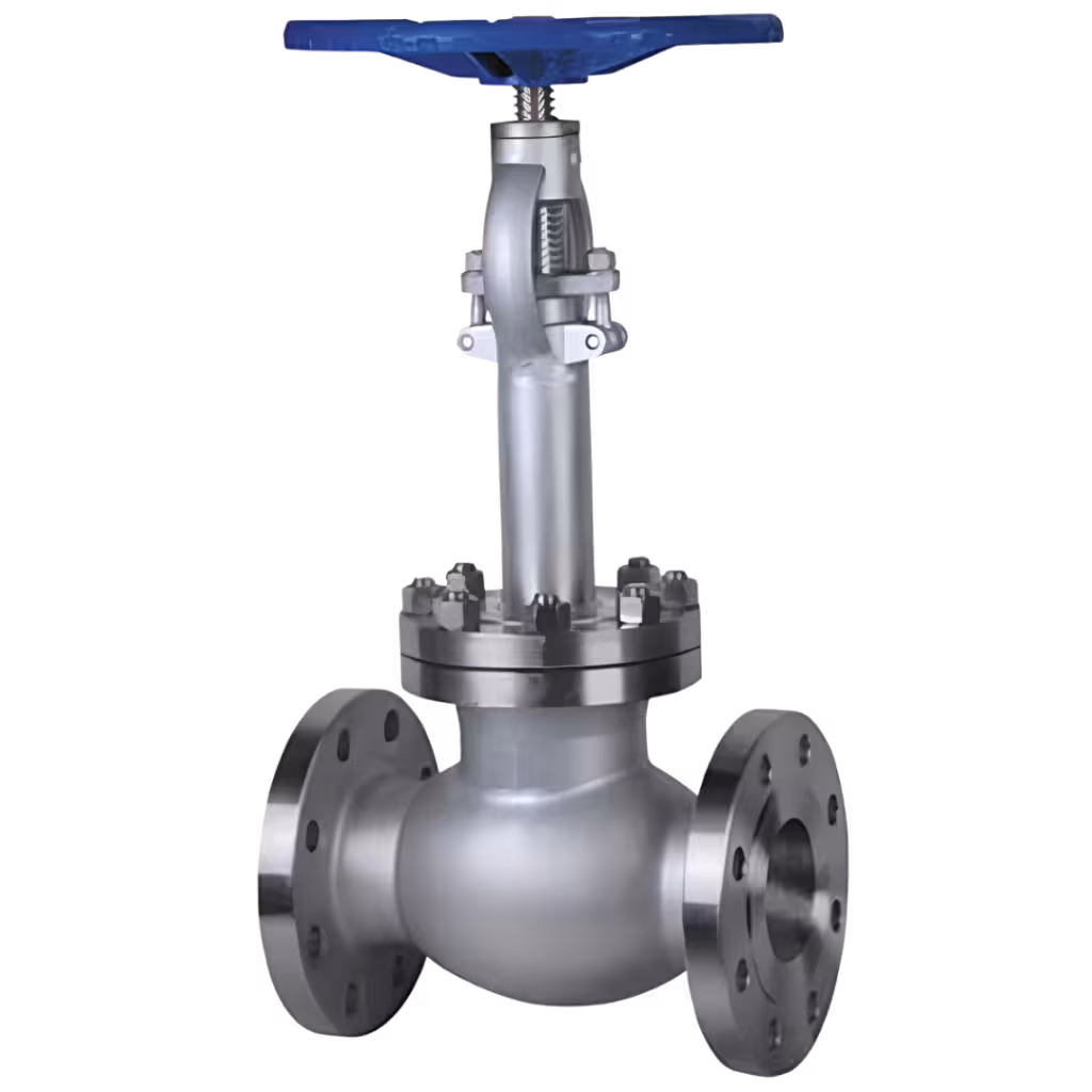
How Ball Valves for Renewable Energy Enhance Fluid Control in Modern Projects
Fluid control in renewable energy projects demands more than conventional valve reliability. System efficiency,...
Key Factors to Consider When Sourcing Aluminum Heat Sink Extrusions for Electronics
Thermal control has become one of the most critical parameters in electronic design today. Modern devices...