
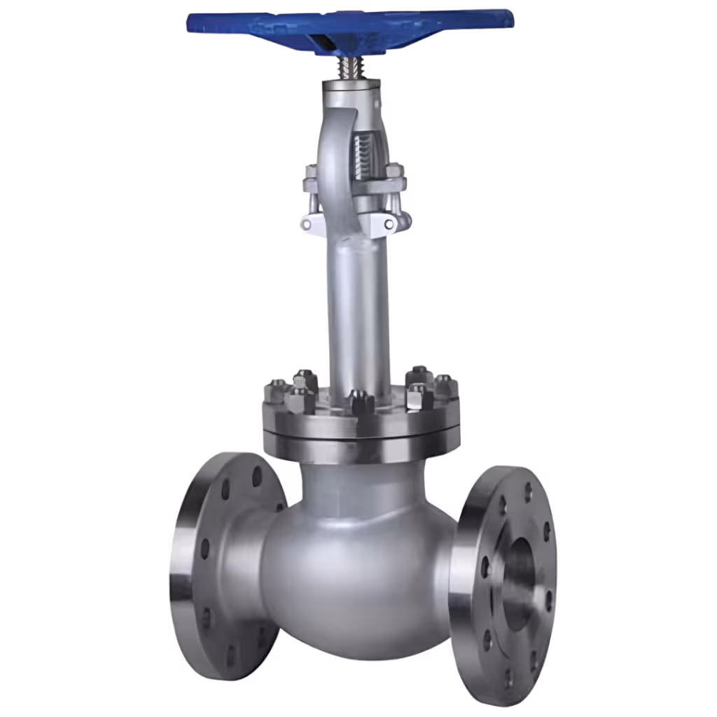


Oil and gas pressure systems operate under extreme mechanical and environmental stress. Subsea trees, wellheads, choke valves, manifolds, and high-pressure connectors often function between 5,000 PSI and 20,000+ PSI. Temperature fluctuations, corrosive fluids, vibration, and cyclic loading further increase operational risk. Under these demanding conditions, even a small machining defect can escalate into leakage, unplanned shutdown, environmental exposure, or serious safety incidents.
Industry reliability assessments indicate that more than 50% of pressure equipment failures are linked to material inconsistencies, machining inaccuracies, or insufficient inspection control. That makes Pressure Component Machining for Oil and Gas a mission-critical engineering function rather than a routine manufacturing step.
Every parameter must be verified. Material, geometry, surface finish, inspection, and compliance must align perfectly. The following sections explain the most critical technical factors that directly influence performance, reliability, and certification success in Pressure Component Machining for Oil and Gas applications.

Why Material Integrity and Full Traceability Are the First Line of Defense
Material selection determines how a pressure component will behave under load, temperature variation, and corrosion exposure. Mechanical strength, fracture toughness, yield properties, and resistance to chemical attack must match the exact service conditions.
Common materials used in Pressure Component Machining for Oil and Gas include –
- ASTM A105 and A350 carbon steels for standard pressure service
- ASTM A182 F51 and F53 duplex and super duplex stainless steels
- Inconel 625 and 718 for high-temperature and corrosive environments
- 316 and 316L stainless steels for moderate corrosion resistance
- Low alloy steels for high-pressure structural strength
Each alloy offers specific performance characteristics. Duplex stainless steel provides higher strength and improved chloride corrosion resistance compared to conventional stainless grades. Nickel-based alloys resist extreme temperatures and aggressive fluids. Carbon steels offer cost efficiency but require protective coatings in corrosive environments.
Material verification must include –
- Positive Material Identification using XRF or Optical Emission Spectroscopy
- Heat number traceability from raw stock to finished part
- Validation of Mill Test Reports
- Hardness testing for sour service conditions
- Compliance with NACE MR0175 requirements
Hydrogen sulfide exposure in sour gas service can cause sulfide stress cracking if hardness exceeds defined limits. Improper material substitution can reduce component life by 30–40%.
Traceability systems must ensure that every machined component can be traced back to its original heat and supplier. Audit delays frequently occur due to documentation gaps rather than physical defects. Strong material governance builds confidence in Pressure Component Machining for Oil and Gas from the foundation upward.
How Dimensional Precision Directly Protects High-Pressure Sealing Performance
Pressure sealing depends on accurate geometry. Uniform gasket compression and correct thread engagement require tight dimensional control.
Critical oil and gas components often demand tolerances within ±0.01 mm to ±0.03 mm. Minor deviations can cause uneven load distribution, which may result in leakage during pressure cycling.
Key dimensional parameters include –
- Flatness of flange faces to ensure uniform gasket seating
- Concentricity of internal bores to prevent misalignment
- Circular runout control for rotating or threaded parts
- Perpendicularity between sealing surfaces and bores
- API thread profile accuracy for secure connections
Geometric Dimensioning and Tolerancing must be applied with precision. Uneven bolt loading may cause gasket extrusion. Misaligned bores can increase internal turbulence and erosion.
Dimensional verification should involve –
- Coordinate Measuring Machine inspection
- In-process probing within CNC machining cycles
- Statistical Process Control monitoring
- Process capability studies using Cp and Cpk metrics
A Cpk value above 1.33 is generally expected for critical pressure components. Higher capability values reduce variation and improve repeatability.
Dimensional non-conformance accounts for nearly one-third of machining-related rework in oil and gas projects. Strong precision control ensures consistent performance in Pressure Component Machining for Oil and Gas systems.
Why Surface Finish and Corrosion Protection Determine Long-Term Durability
Surface quality directly influences sealing reliability, fatigue resistance, and corrosion protection. Microscopic irregularities can act as stress concentration points under cyclic loading.
Sealing faces commonly require surface roughness between 1.6 and 3.2 microns Ra. Excessive roughness may allow leakage paths. Overly smooth surfaces may reduce gasket grip and sealing effectiveness.
Surface integrity management includes –
- Profilometer-based surface roughness verification
- Controlled cutting parameters to avoid tearing or work hardening
- Shot blasting and cleaning prior to coating
- Passivation treatments for stainless steels
- Verification of coating thickness and adhesion
Offshore environments accelerate corrosion due to saltwater exposure and humidity. Improper surface preparation can reduce coating life by up to 40%.
Fatigue cracks often originate at small surface imperfections. Controlled finishing extends service life and reduces maintenance frequency.
Effective surface finishing enhances performance in Pressure Component Machining for Oil and Gas applications operating in aggressive environments.
How Non-Destructive Testing Builds Confidence Before Components Reach the Field
Pressure components cannot be destructively tested. Inspection must detect internal or surface flaws without damaging the part.
Hidden discontinuities such as inclusions, porosity, or micro-cracks can propagate under pressure cycling and lead to sudden failure.
Common NDT methods used in Pressure Component Machining for Oil and Gas include –
- Ultrasonic Testing for internal flaw detection
- Radiographic Testing for volumetric examination
- Magnetic Particle Inspection for surface crack detection
- Dye Penetrant Inspection for non-magnetic alloys
- Hydrostatic testing at 1.5 times design pressure
Hydrostatic tests simulate operating stress conditions. A valve rated for 10,000 PSI may undergo testing at 15,000 PSI to confirm structural integrity.
Quality systems should incorporate –
- Inspection and Test Plans
- Third-party witness coordination
- Calibration control of measuring instruments
- Digital archiving of inspection reports
Structured NDT implementation can reduce catastrophic failure probability by nearly 60–70%. Early flaw detection minimizes repair costs and strengthens field reliability.
Systematic inspection integration increases confidence in Pressure Component Machining for Oil and Gas deliverables.

Why Process Stability and Predictable Lead Times Reduce Operational Risk
Production consistency is as important as technical precision. Prototype approval does not guarantee stable mass production.
Process instability can cause dimensional drift, inconsistent surface finish, and rising scrap rates. Variability disrupts supply chains and increases project costs.
Process control should focus on –
- Tool wear monitoring systems
- Rigid fixture design to prevent movement
- Vibration reduction techniques
- Coolant flow optimization
- Batch-level statistical analysis
Statistical Process Control helps identify deviation trends before they result in defects.
Unplanned downtime in upstream oil and gas operations may exceed $250,000 per day. Delivery delays related to machining variability directly affect revenue and contractual obligations.
Stable and predictable execution strengthens reliability in Pressure Component Machining for Oil and Gas supply chains.
Why Regulatory Compliance and Certification Readiness Cannot Be an Afterthought
Oil and gas pressure components must comply with strict international codes and standards. Certification encompasses both physical integrity and documentation accuracy.
Major regulatory frameworks governing Pressure Component Machining for Oil and Gas include –
- ASME Section VIII
- API 6A
- API 6D
- PED
- ISO 9001
Certification challenges often arise from incomplete records rather than structural defects.
Common compliance risks include –
- Missing inspection documentation
- Incorrect material marking or stamping
- Incomplete heat traceability
- Delays in third-party inspection approval
Proactive documentation management can reduce audit preparation time by nearly 50%. Accurate marking and full traceability simplify regulatory reviews and export approvals.
Strong compliance systems reduce shipment rejection risk and support smooth project execution in Pressure Component Machining for Oil and Gas.
How Frigate Delivers Structured Reliability in Pressure Component Machining for Oil and Gas
Frigate manages Pressure Component Machining for Oil and Gas through a tightly controlled engineering framework. Each stage — from material intake to final certification — follows defined procedures to minimize variation, strengthen traceability, and ensure repeatable high-pressure performance.
Controlled Raw Material Verification and Metallurgical Assurance
Reliability starts with verified materials. Every incoming batch undergoes technical validation before entering production.
Material control includes –
- Positive Material Identification using calibrated XRF or OES
- Chemical composition validation against Mill Test Reports
- Heat number stamping with digital traceability
- Hardness testing for sour service compliance
- Physical segregation to prevent mix-ups
Each component remains traceable to its original heat source. Strong metallurgical control reduces risks such as sulfide stress cracking, hydrogen embrittlement, and premature corrosion in Pressure Component Machining for Oil and Gas applications.
Precision CNC Machining with Process Capability Control
Dimensional accuracy is maintained using multi-axis CNC systems engineered for tight tolerance work on pressure-retaining components.
Precision is supported through –
- Optimized tool paths to limit thermal distortion
- Tool wear monitoring to prevent tolerance drift
- Rigid fixturing to reduce vibration
- In-process probing for live dimensional checks
- Statistical Process Control to maintain high Cp and Cpk values
Capability validation ensures repeatability before scaling production. Stable machining performance strengthens reliability in Pressure Component Machining for Oil and Gas projects.
Integrated Dimensional Inspection and CMM Validation
Dimensional inspection is embedded throughout the machining cycle rather than limited to final checks.
Inspection controls cover –
- Flatness verification of sealing faces
- Concentricity and bore alignment measurement
- Perpendicularity validation of mating surfaces
- API thread profile inspection
- Surface roughness testing
Layered inspection minimizes cumulative deviation and supports consistent compliance.
Structured Non-Destructive Testing Within Production Flow
Non-Destructive Testing is integrated at predefined checkpoints based on Inspection and Test Plans.
Testing capabilities include –
- Ultrasonic Testing for internal discontinuities
- Radiographic Testing for volumetric defects
- Magnetic Particle Inspection for surface cracks
- Dye Penetrant Inspection for non-magnetic alloys
- Hydrostatic testing at specified pressure margins
Early-stage flaw detection reduces late-stage rejection and improves field reliability in Pressure Component Machining for Oil and Gas components.
Compliance-Ready Documentation and Certification Support
Documentation systems are structured to align with ASME, API, PED, and customer-specific standards.
Certification packages typically include –
- Material Test Certificates
- Heat traceability records
- Dimensional inspection reports
- NDT reports with calibration references
- Hydrostatic test certificates
Digitized documentation control streamlines audits and simplifies third-party verification.
Process Validation and Continuous Quality Governance
Pilot runs validate machining stability before full production begins. Fixture rigidity, tool life consistency, and inspection repeatability are confirmed during this stage.
Strategic inspection checkpoints prevent defect accumulation. Deviation management and structured quality reviews support corrective action and continuous improvement.
Systematic control across materials, machining, inspection, and documentation ensures dependable execution in Pressure Component Machining for Oil and Gas under high-pressure operating conditions.

Conclusion
Pressure systems operate with little margin for error. Material integrity, dimensional accuracy, surface quality, inspection rigor, process stability, and regulatory compliance must all align to ensure long-term performance.
Frigate combines precision machining, inspection integration, and compliance-ready documentation to support reliable performance in high-pressure oil and gas environments. Connect with Frigate to strengthen your Pressure Component Machining for Oil and Gas programs and ensure dependable performance under the most demanding operating conditions.