


2.8X
Sourcing Cycle Speed

94 %
On-Time Delivery Rate

4X
Multi-Part Consolidation

22%
Quality Rejection Rate

30%
Procurement Costs

20%
Manual Processing Time

19 Countries
Exported To

250+
Unique Parts Manufactured

50+
Qualified Vendors

ISO 9001 + AS9100D
Certified Standards

5 Core
Manufacturing Processes

15+ Years
Manufacturing Expertise

“I would strongly recommend Frigate to anyone who wants to do Rapid Prototyping, and take their ideas to manufacturing. One firm doing all kinds of Product Development!”
“Top-notch machining and fast shipping. Very satisfied with the results.”
“The next disruption is happening in Prototyping & Manufacturing on-demand and Frigate is leading the way! I personally believe the Frigate's way of IIOT enabled cloud platform with Al.”
“Frigate delivered high-quality parts at a competitive price. The instant quote tool is a huge plus for us!”
“We appreciate the precision and quality of the machined components in the recent delivery—they meet our specifications perfectly and demonstrate Frigate’s capability for excellent workmanship.”
“I am absolutely happy to work with supplier like Frigate who were quite proactive & result oriented . Frigate has high willingness team who has strong know how & their passion towards the products & process were absolutely thrilling.”
“Parts were exactly as spec’d, and the instant quote made budgeting a breeze.”
“Good value for the money.”
“The finish was perfect, and the team was easy to work with.”
“Working with Frigate has been great. Their proactive, results-driven approach and expertise shine through in every project. It's been a pleasure collaborating with them.”
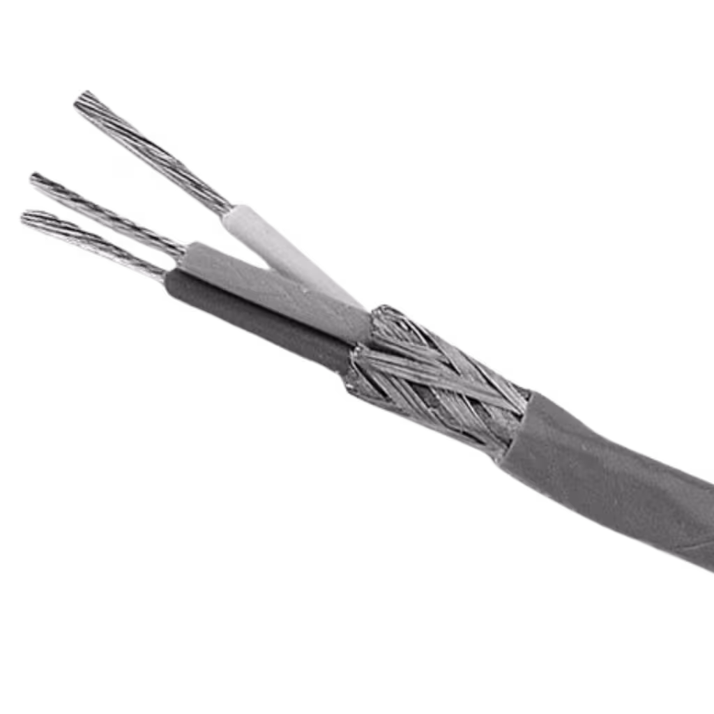
"We are highly satisfied with the timely delivery and quality of the MIG Welding Cable from Frigate. Their attention to detail, secure packaging, and quick responsiveness stood out. We confidently recommend Frigate Engineering Services Pvt. Ltd. as a reliable manufacturing partner."