


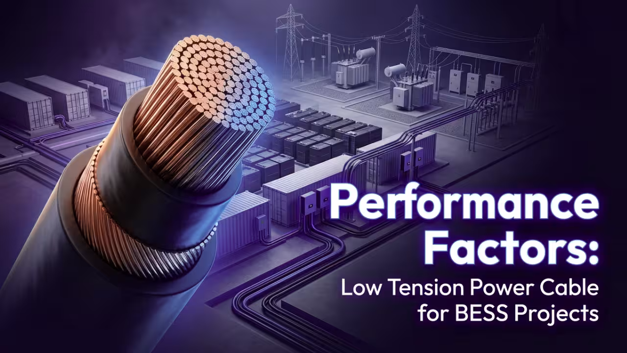
Battery Energy Storage Systems (BESS) are becoming the backbone of renewable energy integration and grid stability. Global energy storage capacity has already crossed 200 GW, and annual growth continues at over 15%. Such rapid deployment increases pressure on every component to perform reliably for 20–25 years. Among these components, the Low Tension Power Cable for BESS plays a direct role in energy efficiency, safety compliance, and operational continuity.
Large BESS installations operate under high current, continuous cycling, elevated ambient temperatures, and compact containerized layouts. Electrical losses of just 1–2% can significantly reduce long-term energy output in utility-scale projects. Thermal stress, harmonics, and fault currents further increase performance demands. A properly engineered Low Tension Power Cable for BESS ensures minimal resistive loss, strong thermal endurance, and stable long-term operation.
Procurement and engineering teams frequently encounter concerns such as overheating, fire safety approvals, voltage drop mismatches, and inconsistent supply quality. Technical understanding of cable performance factors eliminates these risks while protecting lifecycle returns.

Why Electrical Design Precision Defines BESS Cable Performance
Electrical performance determines whether a BESS operates efficiently or wastes energy through heat and losses. Battery racks, DC combiner panels, and inverters draw high current continuously. Cable design must support these conditions without exceeding thermal limits.
Current Carrying Capacity (Ampacity)
Correct conductor sizing forms the basis of cable reliability. A Low Tension Power Cable for BESS must operate safely at conductor temperatures typically rated at 90°C or higher, depending on insulation.
Key design considerations include –
- Conductor cross-sectional area matched to maximum load
- Ambient temperature correction factors
- Cable grouping derating in trays
- Installation method impact on heat dissipation
Thermal aging accelerates rapidly beyond rated limits. A 10°C increase above design temperature can reduce insulation life by nearly half. Precise ampacity calculation prevents premature failure.
Voltage Drop and Energy Loss Control
Voltage drop across long cable runs directly affects inverter performance and overall system efficiency. Acceptable limits typically remain below 2–3%.
Higher voltage drop causes –
- Increased I²R losses
- Additional conductor heating
- Reduced usable battery output
- Lower system efficiency
Optimized conductor resistivity and accurate length planning protect energy yield.
Short Circuit Withstand Capability
Fault currents in BESS installations may reach 25kA to 50kA. A robust Low Tension Power Cable for BESS must withstand intense thermal and mechanical stress during short circuit events until protection systems isolate the fault.
Strong conductor bonding and insulation integrity determine safety during such events.
Copper vs Aluminum Selection
Material selection influences both performance and cost.
- Copper offers higher conductivity and compact sizing
- Aluminum provides weight and cost advantages
Lifecycle analysis often favors copper for high current density systems due to reduced resistive losses over 20+ years.
How Thermal and Fire Safety Performance Protects BESS Assets
Energy storage systems operate with high energy density. Fire safety compliance remains a top priority for regulators, insurers, and project stakeholders. Cable insulation chemistry and sheath design directly influence flame spread behavior.
A compliant Low Tension Power Cable for BESS must meet IEC and UL fire performance standards.
Fire Performance Characteristics
Critical fire-related features include –
- Flame retardant properties
- Low Smoke Zero Halogen (LSZH) insulation
- Controlled flame propagation
- Reduced smoke density
- Low toxicity gas emission
Electrical faults contribute to approximately 20–25% of industrial fire incidents. Flame-retardant insulation limits secondary fire escalation inside containers.
Thermal Stability Under Continuous Load
Containerized BESS units can experience ambient temperatures exceeding 50°C. Conductor temperature may rise above 90°C during heavy cycling.
XLPE insulation provides –
- High dielectric strength
- Improved thermal resistance
- Long-term dimensional stability
Thermal endurance ensures consistent insulation performance across thousands of charging cycles.

What Mechanical Strength and Environmental Resistance Mean for Long-Term Reliability
BESS installations operate across deserts, coastal regions, and cold climates. Environmental exposure becomes a long-term stress factor.
A durable Low Tension Power Cable for BESS must resist physical and chemical degradation.
Environmental Stress Factors
Typical challenges include –
- UV radiation exposure
- Moisture ingress
- Abrasion in cable trays
- Chemical exposure from electrolytes
- Rodent damage risks
UV-stabilized outer sheaths and water-blocking layers prevent early degradation. Moisture ingress remains a leading cause of insulation breakdown.
Flexibility and Routing Efficiency
Containerized layouts offer limited routing space. Adequate bending radius ensures easier installation and reduces termination strain.
Excessive rigidity increases labor effort and potential joint failures. Balanced mechanical design improves both durability and installation practicality.
Why Installation Efficiency Directly Impacts Total Project Cost
Cable selection affects not only material cost but also labor and commissioning schedules. Installation expenses may account for 30–40% of total cabling budgets.
An optimized Low Tension Power Cable for BESS improves handling efficiency and reduces rework risk.
Installation-Focused Design Considerations
Important parameters include –
- Cable diameter and weight
- Ease of stripping and lug termination
- Clear surface marking for identification
- Drum length optimization
- Compatibility with connectors
Large utility-scale projects may require more than 50 km of cabling. Small improvements in handling efficiency can significantly reduce labor hours.
Hidden Costs of Suboptimal Cable Design
Improper cable specification can result in –
- Overheating during peak load
- Excess voltage drop
- Increased maintenance frequency
- Reduced system bankability
Lifecycle cost evaluation offers stronger financial protection compared to lowest-price procurement decisions.
How Lifecycle Durability and Testing Safeguard 25-Year Performance
Most BESS projects are designed for 15–25 years of operation. Cable insulation and conductor systems must match this timeline.
Resistance to Thermal Cycling
Repeated charging cycles create continuous expansion and contraction stress.
A reliable Low Tension Power Cable for BESS demonstrates resistance to –
- Insulation cracking
- Conductor oxidation
- Sheath hardening
- Dielectric strength reduction
High-quality polymer compounds slow aging and extend service life.
Harmonics and Variable Load Conditions
Inverter-based systems generate harmonic currents. Harmonics increase effective RMS current and internal heating.
Proper conductor sizing and insulation grade reduce long-term degradation caused by harmonic distortion.
Testing and Quality Assurance
Comprehensive testing strengthens reliability –
- Type testing
- Routine production testing
- High voltage testing
- Partial discharge measurement
- Flame propagation testing
Documented compliance enhances warranty alignment and lowers project risk.
Why Supply Chain Strength and Engineering Support Matter in Large BESS Deployments
Utility-scale installations require consistent bulk cable supply. Delivery delays directly impact commissioning schedules.
A dependable Low Tension Power Cable for BESS supplier ensures –
- Stable raw material sourcing
- High-volume production capacity
- Consistent conductor purity
- Full compliance documentation
- Engineering support during design stage
Early technical collaboration prevents oversizing, reduces material waste, and enhances electrical efficiency.
How Does Frigate Engineer High-Performance Low Tension Power Cable for BESS Projects?
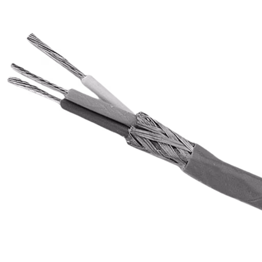
Frigate develops Low Tension Power Cable for BESS with a clear engineering objective – deliver predictable electrical performance, controlled thermal behavior, certified fire safety, and long service life under demanding storage conditions. Battery Energy Storage Systems operate with high current density, continuous cycling, harmonics from inverters, and elevated ambient temperatures inside containers. Cable design must address all these stresses together, not individually.
Engineering Focus on Electrical Precision
Electrical performance begins with conductor design. Frigate optimizes conductor construction to balance conductivity, flexibility, and heat dissipation.
Optimized conductor design for high ampacity –
- High-purity electrolytic grade copper or specified aluminum alloys
- Precisely controlled stranding to reduce AC resistance
- Compacted conductors to reduce diameter and improve current density
- Accurate cross-sectional sizing based on load studies
High ampacity performance ensures the Low Tension Power Cable for BESS can operate continuously at rated load without exceeding thermal limits. Proper conductor geometry also minimizes I²R losses, improving overall BESS efficiency over 20–25 years.
Thermal Endurance Built for Continuous Cycling
BESS installations generate heat from both electrical load and surrounding battery modules. Thermal endurance determines long-term insulation reliability.
XLPE insulation for thermal stability
- Rated for 90°C continuous operation
- Higher short-circuit thermal withstand capacity
- Excellent dielectric strength under fluctuating loads
- Strong resistance to thermal aging
Cross-linked polyethylene (XLPE) provides dimensional stability and maintains insulation integrity even under repeated heating and cooling cycles. Thermal aging resistance directly influences lifecycle performance of the Low Tension Power Cable for BESS.
Fire Performance Designed for Container Safety
Fire safety compliance remains critical for containerized BESS environments. Flame propagation risk must be minimized.
FR and LSZH sheath configurations –
- Flame retardant compounds that restrict fire spread
- Low Smoke Zero Halogen materials to reduce toxic gas emission
- Controlled smoke density to improve evacuation safety
- Compliance with IEC 60332 and related fire performance standards
Reduced halogen emission protects both personnel and sensitive electronic equipment during fault events. Fire-rated sheath systems strengthen overall system compliance and insurance acceptance.
Compliance and Certification Framework
Grid-connected storage systems must comply with international electrical and safety codes.
Compliance with IEC and international standards –
- IEC voltage and insulation performance standards
- Short circuit withstand verification
- Flame propagation and smoke emission testing
- Routine and type test documentation
Structured documentation and certification reduce project approval delays and enhance bankability.
Quality Assurance and Traceability
Consistency across large production volumes is critical for utility-scale projects.
Comprehensive in-house and third-party testing –
- High voltage withstand testing
- Conductor resistance measurement
- Partial discharge testing
- Mechanical and thermal endurance validation
Batch-level traceability ensures each production lot can be tracked to raw material source, processing stage, and testing records. Traceability supports warranty alignment and long-term risk management.
Customization Based on Real Project Conditions
Every BESS project differs in layout, load profile, and environment. Cable configuration must match those specific parameters.
Customized configurations include –
- Conductor size optimization based on voltage drop calculations
- Sheath selection for UV exposure or buried installation
- Armored or unarmored options depending on mechanical risk
- Flexible designs for confined container routing
Frigate’s approach integrates electrical design, material science, fire safety engineering, and supply reliability into one coordinated solution. Such integration ensures that every Low Tension Power Cable for BESS performs consistently across its full operational lifecycle while supporting efficiency, compliance, and long-term asset protection.

Conclusion
Performance of a Low Tension Power Cable for BESS directly influences system efficiency, safety compliance, installation timelines, and long-term operational stability. Electrical precision, thermal endurance, fire performance, mechanical durability, and supplier reliability must be evaluated collectively.
Strategic selection of a technically engineered Low Tension Power Cable for BESS protects asset value and reduces lifecycle risk across 20+ years of operation.
Frigate supports advanced energy storage projects with reliable, performance-focused cable solutions.Connect with Frigate to enhance efficiency, safety, and durability across BESS infrastructure.