







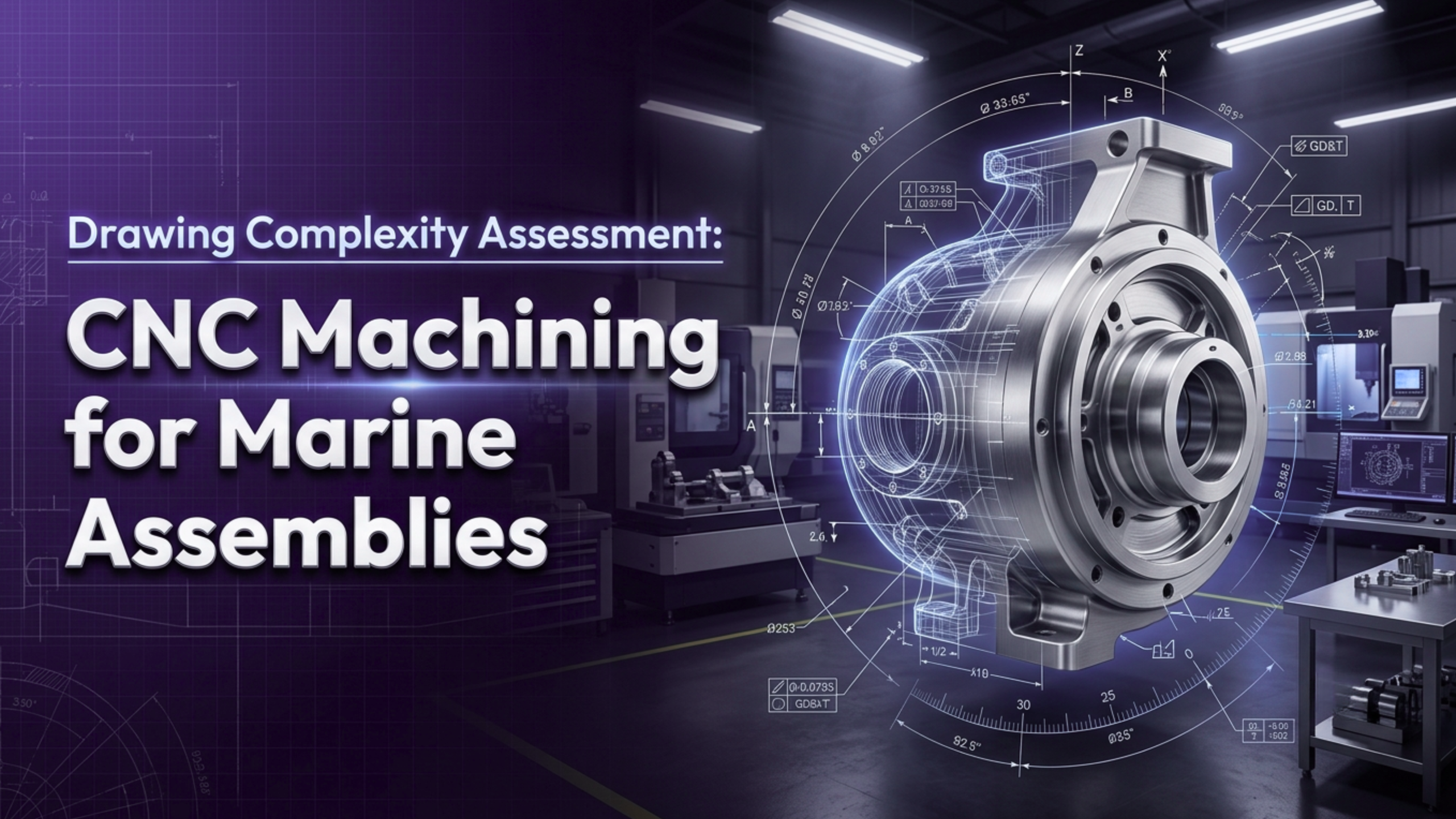
Marine systems operate where failure is not an option. Saltwater accelerates corrosion. Continuous vibration weakens joints. Pressure fluctuations test every sealing surface. Performance depends on precision. That precision begins with the drawing.
CNC Machining for Marine Assemblies demands more than cutting metal to size. Drawings must translate functional requirements into manufacturable geometry. Complex marine assemblies often combine corrosion resistance, tight tolerances, multi-axis features, and strict compliance documentation. Each of these factors adds technical layers to the machining process.
Engineering teams frequently focus on performance. Procurement teams focus on cost and lead time. Manufacturing teams focus on feasibility. Drawing complexity connects all three. When complexity is not evaluated early, cost increases, timelines shift, and quality risk grows.
Structured complexity assessment makes CNC Machining for Marine Assemblies predictable, stable, and scalable.
Why Drawing Complexity Becomes a Critical Risk Factor in Marine Manufacturing
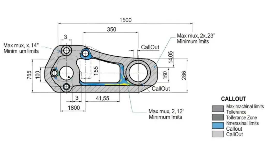
Marine assemblies experience dynamic loads, torsion, bending stress, and temperature shifts. Dimensional accuracy must remain consistent across these conditions. Drawings define that accuracy.
Complexity increases when –
- Multiple tight tolerances interact
- Geometric controls require simultaneous compliance
- Materials are difficult to machine
- Surface finish affects sealing or corrosion resistance
- Assembly fit depends on cumulative dimensional stacking
Tolerance stacking deserves special attention. When multiple parts with tight tolerances assemble together, minor variation in each component can result in misalignment. Shaft runout, flange leakage, or bearing wear may occur even when individual parts are technically within tolerance.
Programming time also grows with complexity. A prismatic 3-axis part may require two hours of CAM preparation. A five-axis marine housing with compound curves and internal cavities may require fifteen to twenty hours of programming. That difference directly impacts project cost and schedule.
Industry research suggests that up to 70% of manufacturing defects originate during design rather than machining. Marine environments amplify that risk because corrosion and vibration expose even minor dimensional deviations.
Drawing assessment forms the foundation of successful CNC Machining for Marine Assemblies.
Technical Drivers That Truly Define Drawing Complexity in Marine Assemblies
Drawing complexity is not just about shape. It is about how geometry, tolerance, material, and finishing requirements interact under real machining conditions.
Tight Tolerances and GD&T Controls
Marine assemblies often require –
- Positional tolerances within ±0.01 mm
- Flatness below 0.02 mm across sealing surfaces
- Concentricity for rotating pump shafts
- Parallelism for mounting brackets
Such requirements increase finishing passes, reduce allowable feed rates, and demand temperature control during machining. Stainless steel expands when heated. Tool deflection under high cutting forces can cause micro-variation. GD&T requirements must align with actual functional necessity.
When tolerances exceed functional needs, cost increases without performance improvement. Careful review ensures efficient CNC Machining for Marine Assemblies while maintaining structural integrity.
Marine-Grade Materials and Machining Behavior
Corrosion resistance defines material selection in marine engineering. Common alloys include stainless steel 316L, duplex stainless steel, aluminum 5083, bronze alloys, and nickel-based materials.
Duplex stainless steel presents unique machining challenges –
- High strength increases cutting force
- Work hardening reduces tool life
- Heat concentration affects dimensional stability
Machinability index for duplex steel can be 30–40% lower than carbon steel. Tool selection, coating type, coolant flow, and cutting parameters must be optimized. Material selection directly impacts cycle time and scrap probability.
Material behavior is central to complexity in CNC Machining for Marine Assemblies.
Multi-Axis Geometry and Structural Weight Optimization
Marine components often integrate multiple functions into a single machined body. Deep cavities reduce weight. Integrated channels improve flow. Complex curves improve structural strength.
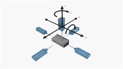
Such features require 4-axis or 5-axis CNC machining. Multi-axis machining reduces setups but increases programming and fixture requirements. Rigidity becomes critical. Thin walls may deflect during machining. Tool chatter may degrade surface finish.
Complex geometry increases risk of dimensional drift. Rigorous process planning ensures stability in CNC Machining for Marine Assemblies.
Surface Finish and Protective Treatment Considerations
Surface finish in marine components is functional rather than cosmetic. Sealing faces require controlled roughness to prevent leakage. Structural parts may need specific texture to support coating adhesion.
Coating thickness influences final dimensions. Anodizing, passivation, or marine-grade coating can add 20–50 microns. Drawings must compensate for this buildup. Failure to consider coating impact often results in post-processing dimensional nonconformance.
Surface engineering significantly contributes to drawing complexity in CNC Machining for Marine Assemblies.
What Hidden Risk Areas Increase Failure Probability During Machining?
Risk in marine machining often originates from material stress and process instability. Large components contain residual internal stress from forging or casting. Rough machining releases that stress and causes warping.
Key risk areas include –
- Distortion after stress relief
- Thermal expansion affecting tight tolerances
- Tool chatter impacting surface integrity
- Post-coating tolerance deviation
- Cumulative tolerance stack in assembly
Thin aluminum housings may bend under clamping pressure. Stainless steel components may shift dimensionally after cooling. Heavy brackets may require intermediate stress-relief heat treatment to maintain geometry.
Dimensional variation of even 0.02 mm can lead to vibration imbalance in rotating assemblies. Warranty costs in marine equipment often exceed initial manufacturing cost by several multiples.
Risk mitigation begins with comprehensive drawing review in CNC Machining for Marine Assemblies.
How Drawing Specifications Directly Influence Cost Structure and Lead Time
Cost drivers are embedded within drawings. Complexity increases resource consumption.
Major contributors include –
- Extended CAM programming hours
- Custom fixture design and validation
- High-performance carbide tooling
- Reduced feed rates for finishing
- Increased CMM inspection time
Inspection time grows with feature count. A part containing fifty controlled dimensions may require longer inspection than machining itself. CMM programming and verification add further overhead.
Additional cost pressures arise from –
- High tool wear in duplex materials
- Secondary operations such as polishing
- Multiple setups to maintain precision
- Scrap generated by tolerance misinterpretation
Industry data indicates tight tolerance components may increase manufacturing cost by 25–40% compared to moderate tolerance parts.
Transparent complexity evaluation improves cost predictability in CNC Machining for Marine Assemblies.
How Can Practical Design Optimization Balance Performance and Manufacturability?
Complexity does not always translate into better performance. Many marine drawings contain over-constrained tolerances.
Optimization strategies improve efficiency while maintaining durability –
- Apply tight tolerances only to function-critical interfaces
- Replace sharp internal corners with machinable radii
- Standardize hole diameters to match common tooling
- Limit ultra-smooth finishes to sealing surfaces
- Separate large assemblies into modular sub-components
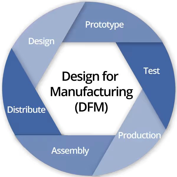
Design for Manufacturability (DFM) review aligns functional requirements with machining capability. Relaxing tolerance from ±0.01 mm to ±0.03 mm where acceptable can significantly reduce cycle time.
Finite element analysis may confirm structural integrity under adjusted tolerance levels. Balanced design reduces engineering changes and procurement delays.
Such refinement enhances stability in CNC Machining for Marine Assemblies.
How Frigate Systematically Manages Drawing Complexity in CNC Machining for Marine Assemblies?
Frigate manages drawing complexity through a structured, engineering-led approach. Every project begins with a technical feasibility review before machining is approved. This prevents downstream cost escalation and dimensional risk in CNC Machining for Marine Assemblies.
Below is a concise but technically detailed breakdown of the methodology.
Detailed GD&T Validation
Frigate analyzes the drawing based on functional intent and assembly conditions.
- Datums are verified to ensure they reflect real mounting and sealing conditions.
- Feature Control Frames are checked for practicality and alignment with machining capability.
- Redundant or conflicting tolerances are identified early.
- Critical features are separated from non-critical ones to prevent over-specification.
This validation ensures tolerances are achievable and aligned with performance requirements in CNC Machining for Marine Assemblies.
Tolerance Stack-Up Simulation
Marine assemblies often contain multiple precision components. Frigate evaluates how dimensional variation accumulates across mating parts.
- Linear and angular tolerance chains are calculated.
- Worst-case and RSS stack-up analysis is performed for critical fits.
- High-risk features affecting alignment, sealing, or rotation are flagged.
This analysis reduces assembly misalignment and prevents functional failure caused by cumulative deviation.
Machinability Assessment for Marine Alloys
Marine-grade materials behave differently under cutting loads. Frigate assesses –
- Material hardness, strength, and work-hardening characteristics.
- Heat generation and its impact on dimensional stability.
- Tool wear patterns for duplex, super duplex, and stainless alloys.
Cutting parameters, tooling grade, and coolant strategy are selected accordingly. This improves cycle predictability and reduces scrap during CNC Machining for Marine Assemblies.
Multi-Axis Machining Strategy Development
Complex marine parts often require 4-axis or 5-axis machining. Frigate defines –
- Optimal part orientation to maintain datum consistency.
- Use of 3+2 indexing versus full 5-axis simultaneous machining.
- Toolpath strategies that minimize deflection and collision risk.
Simulation software validates tool movement before production. This improves geometric accuracy across complex surfaces.
Large or thin-wall marine components are prone to stress-related deformation. Frigate mitigates this by –
Distortion Risk Evaluation
- Planning balanced material removal during roughing.
- Recommending stress-relief heat treatment when required.
- Leaving finish allowances for final stabilization cuts.
- Designing rigid fixtures to limit clamping distortion.
Such planning maintains dimensional control throughout CNC Machining for Marine Assemblies.
Inspection Planning Integration
Inspection strategy is defined alongside machining strategy.
- Critical-to-quality features are identified early.
- CMM programs mirror machining datums to avoid interpretation gaps.
- In-process checks are integrated to prevent late-stage rejection.
- Inspection fixtures are designed for repeatability and stability.
This integration ensures traceable, reliable dimensional verification.
Advanced CNC Capability and Controlled Process Execution
Frigate supports complex marine work with –
- Multi-axis CNC machines with high positional accuracy.
- Tool presetting systems for consistent tool geometry control.
- Temperature-managed environments for machining and inspection.
- Documented process sheets and controlled CNC program revisions.
Statistical monitoring of dimensional data helps detect drift before it becomes nonconformance.
Early DFM Collaboration and Risk Control
Frigate engages in early Design for Manufacturability discussions to –
- Optimize tolerances without compromising function.
- Simplify features that increase tool deflection or setup changes.
- Standardize repeatable geometries across part families.
Structured change management and documented workflows maintain consistency from prototype to batch production.
This systematic framework ensures technical reliability, cost predictability, and process stability in CNC Machining for Marine Assemblies.
Conclusion
Drawing complexity directly determines technical feasibility, cost control, and operational reliability. Marine assemblies demand precision under extreme environmental conditions. Tight tolerances, corrosion-resistant materials, and multi-axis geometries elevate machining difficulty.
Structured evaluation transforms complexity into predictable execution. Comprehensive drawing analysis reduces scrap, prevents delays, and strengthens compliance readiness.
Frigate delivers systematic drawing complexity assessment, precise multi-axis machining, and robust inspection capability for demanding marine applications. Connect with Frigate to evaluate upcoming marine assembly projects and achieve controlled, dependable manufacturing outcomes.