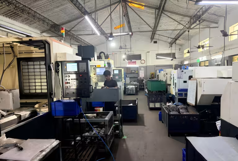
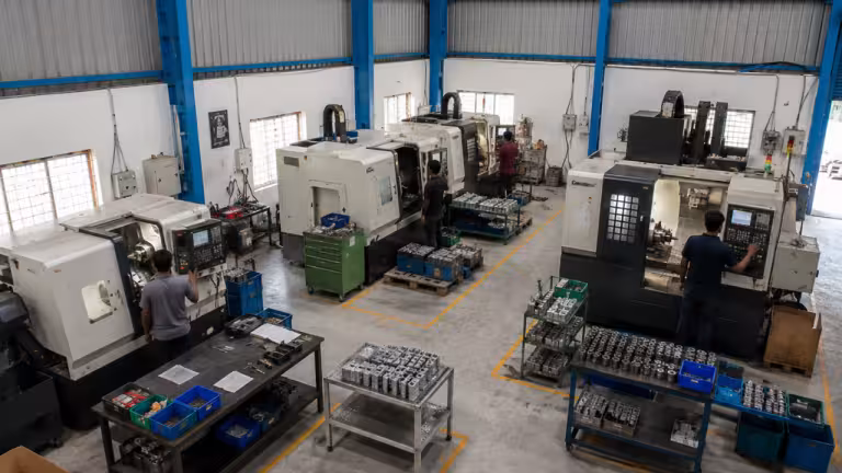
High-precision manufacturing capabilities for metal, plastic, electrical, and assembly requirements.
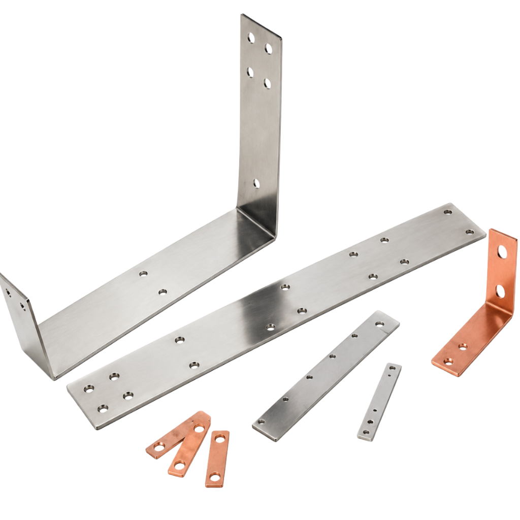
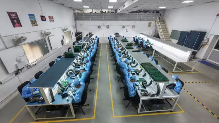
Manufacturing support for precision parts, assemblies, and production-ready components across demanding industries.
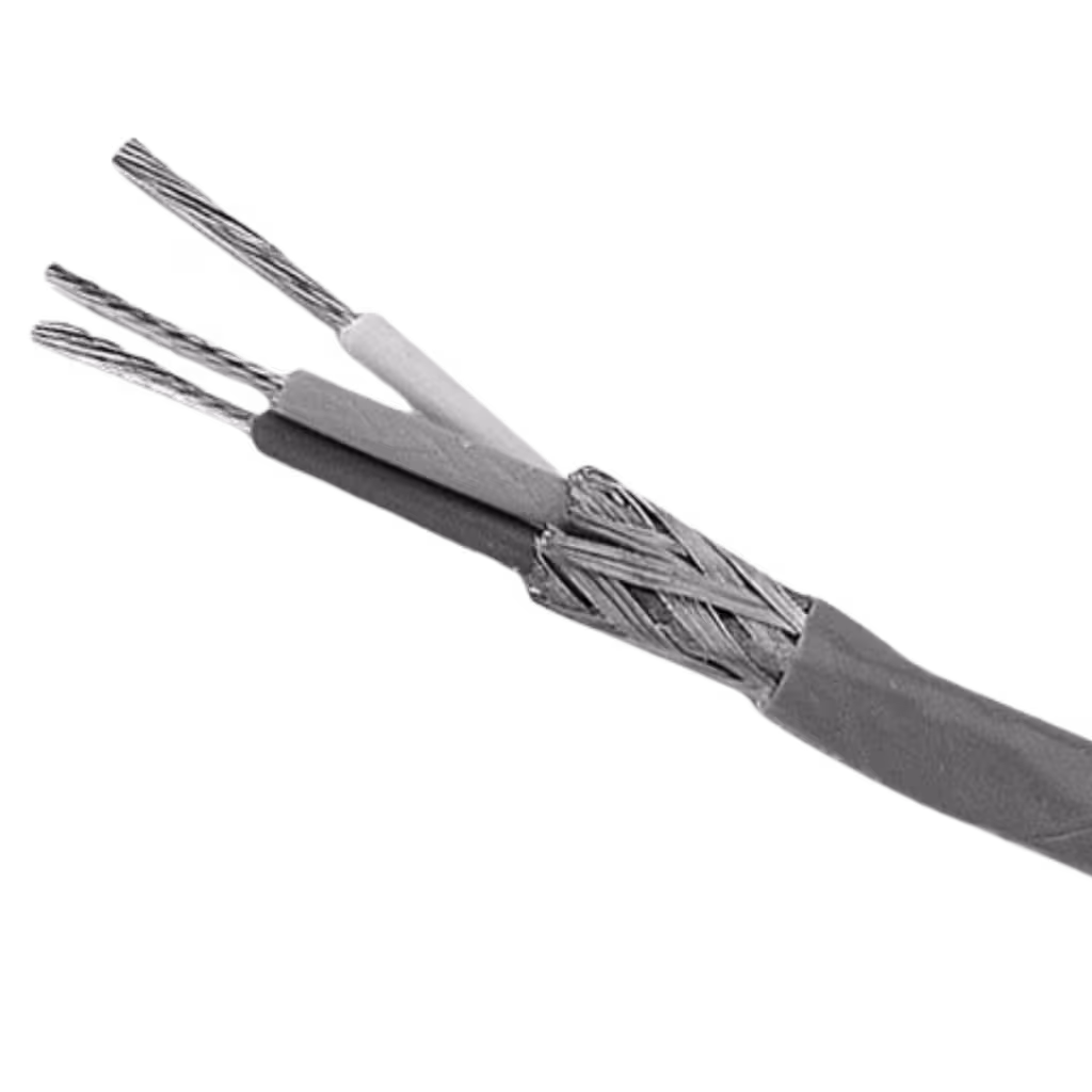
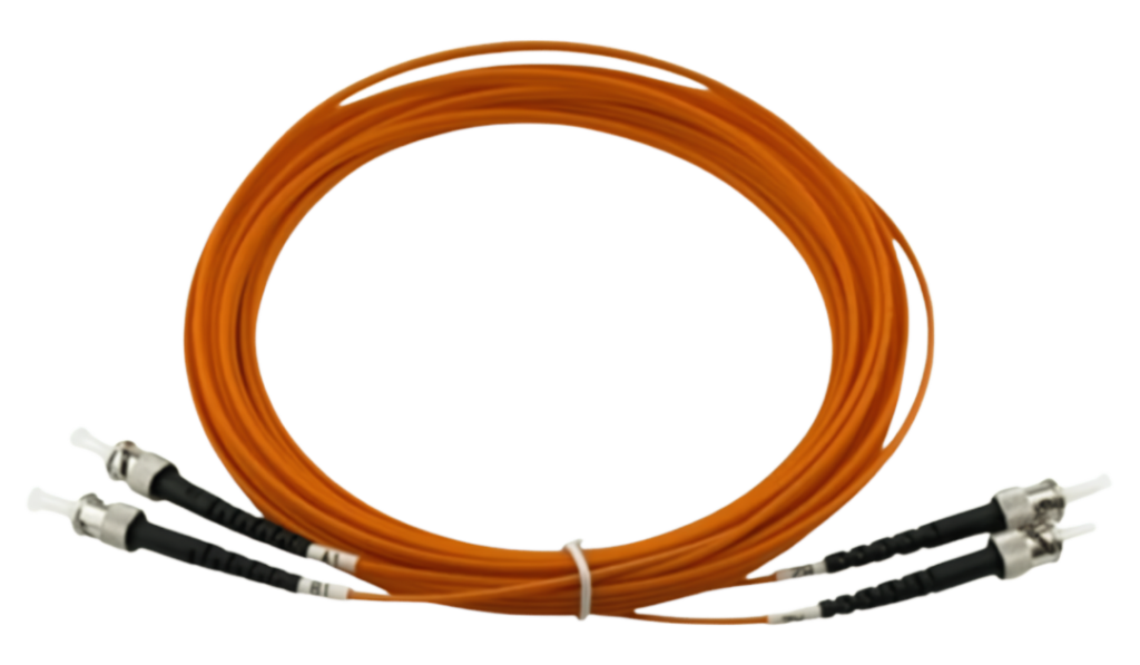
Manufacturing support for enclosures, Bento Box assemblies, cables, wiring harnesses, and BESS components.
High-strength fasteners, landing gear parts, and structural assemblies.
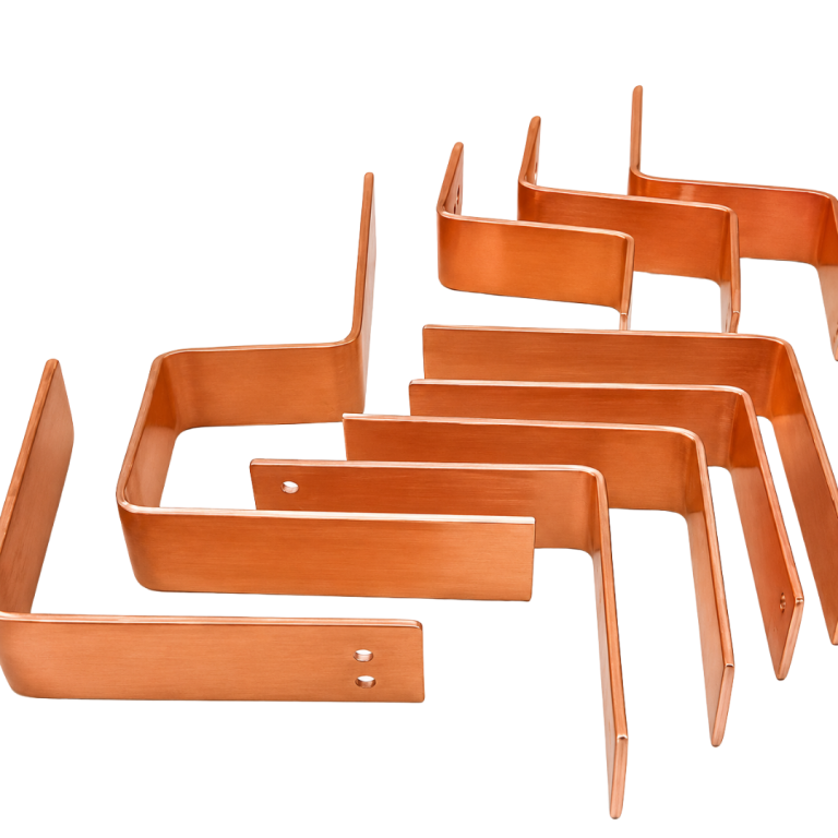
Metal frames, brackets, and assemblies for appliances and home equipment.
Forged housings, armor brackets, and mission-critical structural parts.
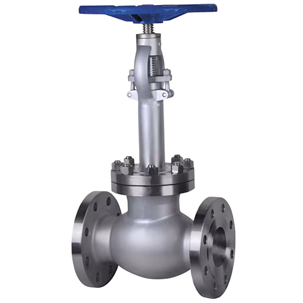
Valve bodies, flange blocks, and downhole drilling components.
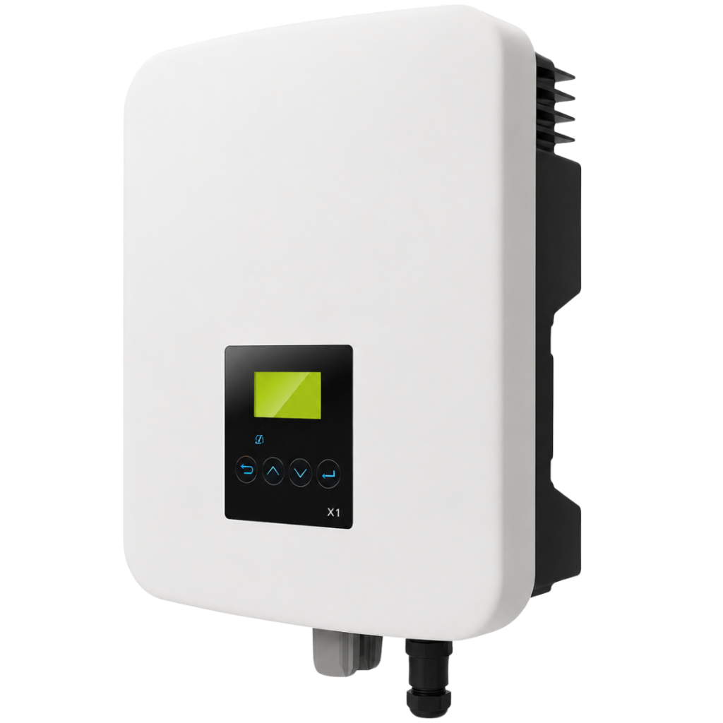
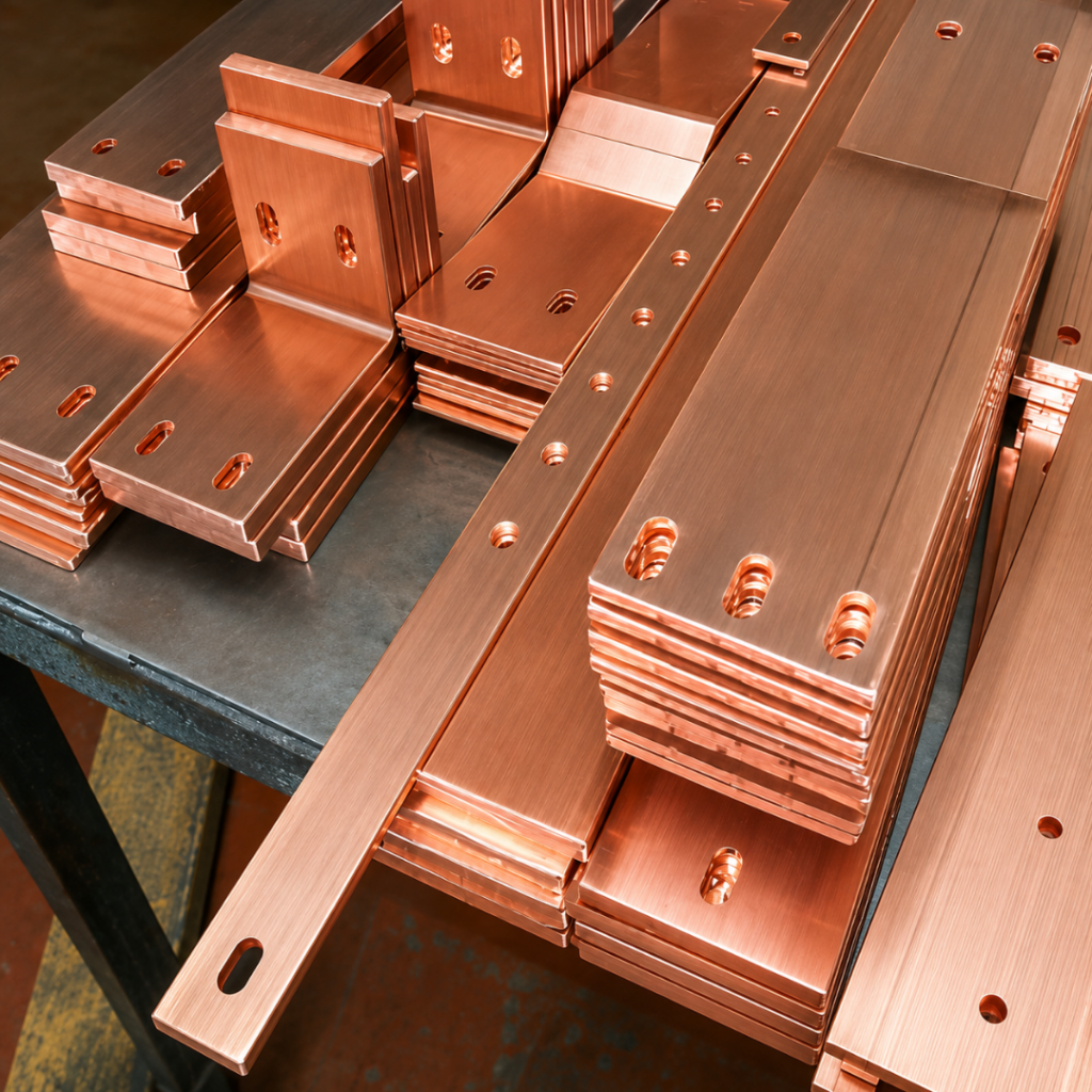
Solar mounting parts, wind turbine brackets, and battery enclosures.
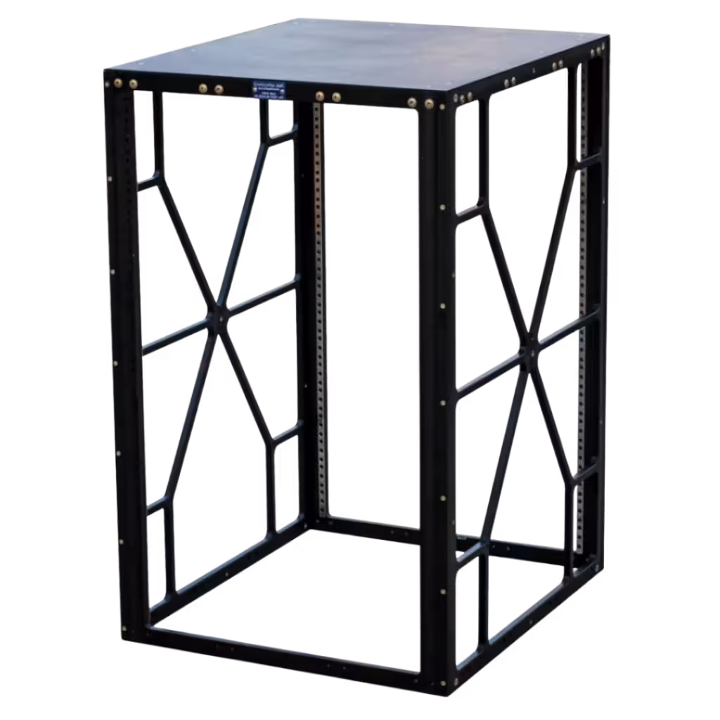
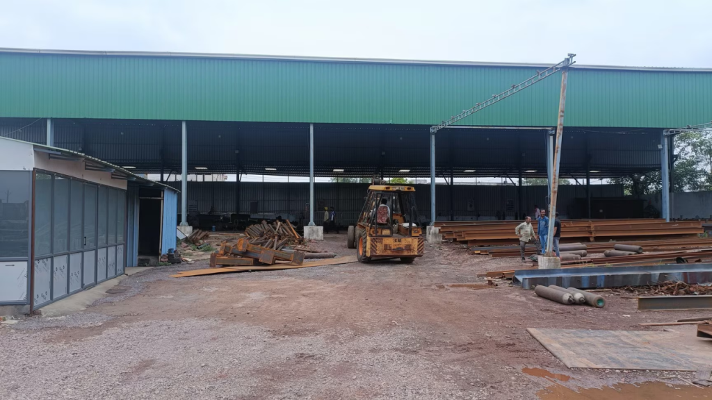
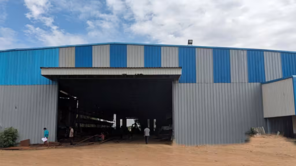
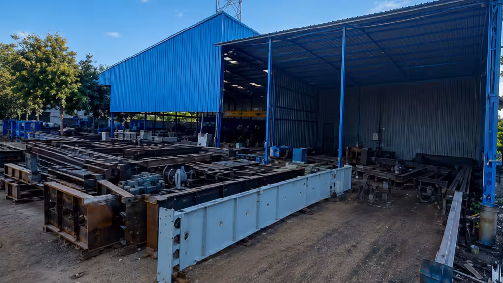
Large welded frames, PEB structures, and assemblies for industrial equipment.
Enclosure and busbar system supplied as a single verified sub-assembly — copper or aluminium conductors installed, torqued, shrouded, and phase-barrier fitted inside the enclosure before dispatch. Connection interface geometry, joint torque values, phase barrier completeness, and thermal performance at rated current are all verified and documented. Arrives at your production line ready for circuit breaker, MCCB, or switchgear connection — no busbar assembly, no torque sequence, no shrouding work on your line.
Frigate installs busbar conductors to your layout drawing with connection interface positions held to ±0.5 mm from the switchgear interface datum. All bolted joints are torqued to specification using calibrated torque tooling and recorded on a per-joint torque verification sheet supplied with every sub-assembly. Contact face plating — tin or silver — is applied per your specification before assembly and verified by plating thickness measurement before installation. Phase barriers and shrouding are fitted to provide full live part isolation before the sub-assembly is packaged for dispatch.
Main distribution board (MDB) and main LV panel sub-assemblies typically carry the highest current ratings in the range — 1,600 A to 6,300 A — with flat copper or aluminium conductor busbars on insulated supports across the full panel width. The connection interface positions for incoming ACB, outgoing MCCB feeders, and inter-panel links are all CNC-drilled to your layout drawing and verified by CMM before dispatch.
Sub-distribution board (SDB) and final distribution sub-assemblies operate in the 100 A to 1,600 A range with smaller cross-section conductors and higher device connection point density — connection position consistency at this density is particularly critical, as small positional errors multiply across a high device count.
Need reliable Enclosure for your next project? Get in touch with us today, and we’ll help you find exactly what you need!
High-current busbar sub-assemblies for main LV switchboard and MDB production — 1,600 A to 6,300 A configurations with ACB incoming interfaces and MCCB feeder connection positions pre-drilled and plated. Torque documentation supports IEC 61439 type-tested assembly verification.
Vertical riser and horizontal tee-off busbar sub-assemblies for MCC production. Tee-off connection positions drilled to your starter unit interface drawing; shrouding between positions completed before dispatch. Consistent tee-off geometry across all positions reduces starter unit alignment time on your production line.
Dual-source busbar sub-assemblies with structural isolation barrier between normal and standby supply zones. Isolation barrier fabricated as a permanent element of the sub-assembly. Both source connection interfaces pre-drilled and plated before dispatch.
Medium-density busbar sub-assemblies for SDB and final distribution panel production — 100 A to 1,600 A range with high device connection point count. Connection position consistency at high device density is maintained through retained jig tooling across all production batches.
Busbar sub-assemblies with CT primary connection interfaces and CT mounting provisions integrated into the conductor layout. CT primary interface positions drilled to ±0.3 mm from busbar centreline per your CT specification.
Enclosure sub-assemblies with busbar trunking connection flanges pre-installed at the trunking entry position. Connection flanges drilled and plated to the trunking manufacturer’s interface specification — tap-off connection at your facility without enclosure modification.
At Frigate, quality is built into every stage of manufacturing. Our approved Quality Management System ensures that every material component.
Before production begins, all incoming materials are checked against specifications, drawings, and supplier documents.
Quality is monitored during manufacturing to prevent defects and maintain process consistency.
Finished parts are inspected before dispatch to confirm compliance with customer drawings and tolerances.
Finished components are packed safely to prevent damage during handling and transportation.
To help buyers evaluate our quality systems, we provide sample documents that reflect our inspection and reporting standards.
Complex geometries engineered solutions that move businesses forward.
Connection position variation between units almost always traces to conductors being positioned by hand against the drawing rather than against a retained jig. Frigate installs conductors using dedicated jig tooling referenced to the enclosure datum — the jig is retained between production batches, not rebuilt each run. Connection position is verified by CMM at first article and AQL-sampled in production, with measurement data available per batch.
Frigate recommends plating specification at DFM review based on your rated current, joint temperature rise target, and contact resistance requirement. Tin plating is standard for configurations up to approximately 2,000 A. Silver plating is recommended above 2,000 A and wherever minimum contact resistance is a specific requirement. The recommendation is included in the written DFM review returned within 5 working days of drawing submission.
Frigate supplies a per-joint torque verification sheet with each sub-assembly — identifying every bolted joint by position reference, the specified torque value, and the measured torque value recorded at assembly. The format is aligned to IEC 61439-1 assembly verification documentation requirements and can be formatted to your incoming quality documentation standard on request.
Submit your busbar layout drawing — conductor positions, cross-sections, connection interface dimensions, support positions, and phase barrier requirements — alongside your rated current, rated voltage, and short-circuit withstand requirement. If a current layout drawing doesn’t exist, Frigate’s engineering team can develop one from your panel schedule and device connection data. DFM review and scope confirmation are returned within 5 working days.
All panel types are managed under a single programme — consistent conductor material specification, matching plating, unified torque documentation format, and a single documentation package structure across all configurations. Each panel type has its own jig tooling and first article, but the programme management, delivery scheduling, and quality documentation are consolidated. The commercial discussion covers whether all panel types enter the programme simultaneously or are phased in as their respective layouts are confirmed.
Submit the form below and our representative will be in touch shortly.
10-A, First Floor, V.V Complex, Prakash Nagar, Thiruverumbur, Trichy-620013, Tamil Nadu, India.
9/1, Poonthottam Nagar, Ramanandha Nagar, Saravanampatti, Coimbatore-641035, Tamil Nadu, India. ㅤ
10-A, First Floor, V.V Complex, Prakash Nagar, Thiruverumbur, Trichy-620013, Tamil Nadu, India.
9/1, Poonthottam Nagar, Ramanandha Nagar, Saravanampatti, Coimbatore-641035, Tamil Nadu, India. ㅤ
Need reliable wires and cables for your next project? Get in touch with us today, and we’ll help you find exactly what you need!
Need reliable Machining for your next project? Get in touch with us today, and we’ll help you find exactly what you need!