CNC Milling Services for R&D and Prototyping
Frigate produces low-volume, precision CNC-milled metal components to support iterative development across complex R&D and prototyping programs. Our flexible setups and tight-tolerance control help you reduce redesign cycles and maintain accuracy at every stage.
Our Clients


- Prototype-Centric Manufacturin
What Our CNC Milling Services Offer
Our CNC milling services address core prototype challenges, including low batch viability, fast changeover, and rapid geometric verification.
Thin-Wall Machining
Controlled material removal enables accurate pocket milling on thin-walled sections with minimal distortion during cooling or load testing.
Iterative Design Fitment
We maintain consistent datum referencing to help match updated CAD revisions with earlier batch geometry during assembly alignment testing.
Feature Complexity Management
High-speed toolpaths and indexed multi-axis control allow us to produce slots, cavities, and contours typically reserved for post-processing.
- Workflow Control
Our CNC Milling Process
Our process focuses on quick adaptability, repeatability across batches, and part consistency during design revisions.

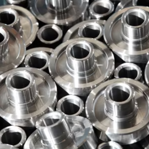
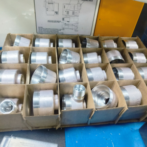
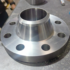

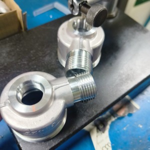
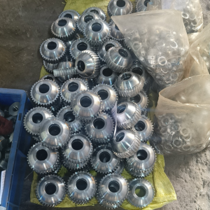
Engineers design the part using CAD (Computer-Aided Design) software. The design includes all dimensions and specifications.
The CAD design is converted into CNC code, often using CAM (Computer-Aided Manufacturing) software. This code tells the milling machine how to move and cut the material.
Operators prepare the CNC milling machine by securing the material (workpiece) and installing the appropriate cutting tools.
The CNC machine reads the code and starts milling. The cutting tool rotates and moves along multiple axes to remove material from the workpiece and shape it into the desired part.
The machine monitors the cutting operations throughout the process. Operators may make adjustments to ensure precision and quality.
After milling, the part may undergo additional processes like deburring or polishing to achieve the final specifications.
The finished part is thoroughly inspected to meet all design requirements and tolerances.
- Real Impact
Words from Clients
See how global OEMs and sourcing heads describe their experience with our scalable execution.
“Quick turnaround and solid quality.”
“The instant quote tool saved us time, and the parts were spot-on. Highly recommend Frigate!”
“Great service, fair price, and the parts worked perfectly in our assembly.”
“Top-notch machining and fast shipping. Very satisfied with the results.”
“Frigate delivered high-quality parts at a competitive price. The instant quote tool is a huge plus for us!”
“We appreciate the precision and quality of the machined components in the recent delivery—they meet our specifications perfectly and demonstrate Frigate’s capability for excellent workmanship.”
“Flawless execution from quote to delivery.”
“The precision on these parts is impressive, and they arrived ahead of schedule. Frigate’s process really stands out!”
“Parts were exactly as spec’d, and the instant quote made budgeting a breeze.”
“Good value for the money.”
“The finish was perfect, and the team was easy to work with.”
- Dimensional Finish Accuracy
Surface Outcomes for Prototypes
We use controlled tool engagement, in-cycle inspection, and programmable offsets to achieve repeatable surface consistency across prototype parts.
Anodizing
Give your aluminum parts a tough, corrosion-resistant shield with anodizing, reaching surface hardness up to HV 500, while enhancing electrical insulation and durability.
Mechanical Finishing
Smooth out imperfections and refine surfaces to Ra 0.2 µm or better with mechanical finishing techniques like grinding, polishing, and bead blasting.
Heat Treatment
Boost material strength and hardness by heat treating parts at temperatures up to 1100°C, ensuring they meet the mechanical demands of your application.
Electroplating
Add protective or functional metal coatings with electroplating, delivering consistent layers as precise as ±2 µm for improved corrosion resistance and conductivity.
Our Machined Products
We support your production needs with CNC-machined parts, subassemblies, and performance-critical components.
- Materials for R&D-Driven CNC Milling
CNC Milling Materials
We work with an optimized range of metals used in research and testing programs. Each alloy brings distinct benefits for strength, machinability, and design feedback.
- Aluminum 6061 supports fixture prototyping due to high machinability and dimensional responsiveness.
- Stainless 17-4PH provides strength and corrosion resistance for mechanical load verification samples.
- Copper alloys enable effective EMI shielding performance during enclosure mockups.
A2 Tool Steel is a high-carbon, high-chromium steel known for its toughness and wear resistance. It’s ideal for producing durable, high-strength parts that can withstand heavy use.
Aluminum is a lightweight, corrosion-resistant metal with good machinability. Because of its strength-to-weight ratio, it’s commonly used in aerospace, automotive, and various industrial applications.
Brass is a copper-zinc alloy known for its machinability and corrosion resistance. It’s used for components requiring precise detailing and good mechanical properties.
Bronze is a copper-tin alloy with excellent wear resistance and strength. It’s often used for bushings, bearings, and other friction-prone components.
Cast Iron is known for its high wear resistance and machinability. It’s used in heavy-duty applications such as machinery parts and engine components.
Copper offers excellent thermal and electrical conductivity. It’s used in applications requiring heat dissipation or electrical conductivity, such as electronic components.
Steel is a versatile material known for its strength and durability. It’s used in various applications, from construction to automotive parts.
Titanium is a lightweight, high-strength metal with excellent corrosion resistance. It’s used in aerospace, medical implants, and high-performance engineering applications.
Stainless Steel offers high corrosion resistance and strength. It’s widely used in applications ranging from kitchen equipment to industrial machinery.
Zinc is a ductile and corrosion-resistant metal known for its excellent machinability, especially in its alloy forms. It's often used for components requiring intricate details, good surface finish, and precise dimensions, commonly found in automotive, hardware, and electrical applications.
- Prototype-Driven Dimensional Control
Precision Parameters That Support R&D Objectives
Our tolerancing protocols, fixturing strategies, and spindle feedback systems reduce failure points in short-run, iterative part manufacturing. This approach supports consistent prototype validation across design iterations. It also reinforces tolerance stack-up integrity during component integration testing.
- Hole location accuracy within ±0.01 mm improves reference consistency during assembly benchmarking.
- Face milling flatness within 0.015 mm supports parallel plate stack-ups in electrical enclosure trials.
- Positional tolerances maintained across multiple axis setups for multi-step cut prototypes.
- Allows zero-offset repeat part production using stored digital part programs.
- Enables minimal-remnant strategy for material conservation during exploratory milling.

- Standards and Verification
Compliance for CNC Milling Services
Frigate’s CNC milling solutions are structured to comply with R&D protocol expectations for traceability, repeatability, and standard-based validation. Our setups support lab testing, pre-certification prototyping, and first-article documentation. Processes are structured to meet material control, geometry verification, and early-stage safety benchmarks.
- Aligns to regulatory screening stages in functional hardware trials.
- Retains full revision logs and part serials per test protocol.
- Supports early batch-level RoHS and CE conformity pre-screening.
Supports repeatable production practices and documented quality control across R&D builds.
Applies to aerospace-related research or part testing involving mission-critical geometry.
Limits hazardous material use across parts intended for electronics testing or medical environments.
Helps validate early-stage component designs for future EU market introduction.
Applied when machining involves post-processing intended for aerospace-grade certification.
Supports component traceability in automotive research programs.
Allows build programs to simulate safety compliance in regulated prototype assemblies.
- We export to 12+ countries
Frigate’s Global Presence
Frigate takes pride in facilitating “Make in India for the globe“. As our global network of Frigaters provides virtually limitless capacity, and through our IoT enabled platform your parts go directly into production. By digitally and technologically enabling “the silent pillars of the economy” MSME and SME manufacturing industries, we are able to tap the huge potential for manufacturing to bring the best results for our clients.

100,000+
Parts Manufactured
250+
Frigaters
2000+
Machines
450+
Materials
25+
Manufacturing Process

- Controlled Inspection and Testing
Quality Testing Standards for CNC Milling Services
To measure the roundness of cylindrical features, ensuring they meet tolerance requirements.
To check internal surfaces for flatness, critical for sealing and assembly purposes.
To identify burrs or sharp edges that may affect assembly or safety.
To ensure that complex profiles (e.g., contours, curves) conform to design specifications.
To check the topography and texture of the surface, ensuring it meets the required specifications for function or aesthetics.
To verify that the surface hardness depth meets the required specifications for wear resistance.
To measure internal stresses that could lead to deformation or failure during or after machining.
To verify grain structure, inclusions, and material consistency, ensuring the part meets performance requirements.
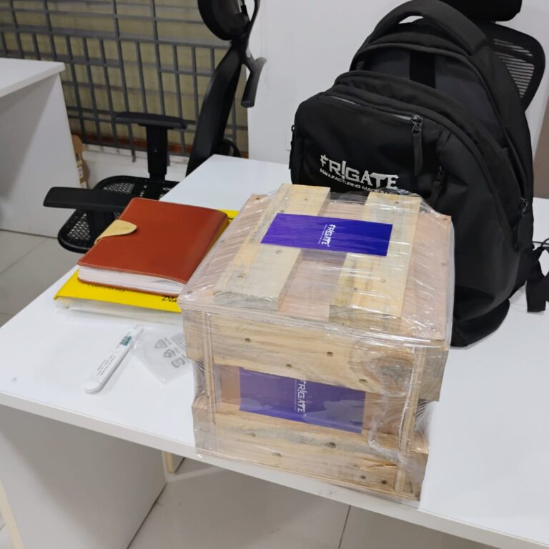
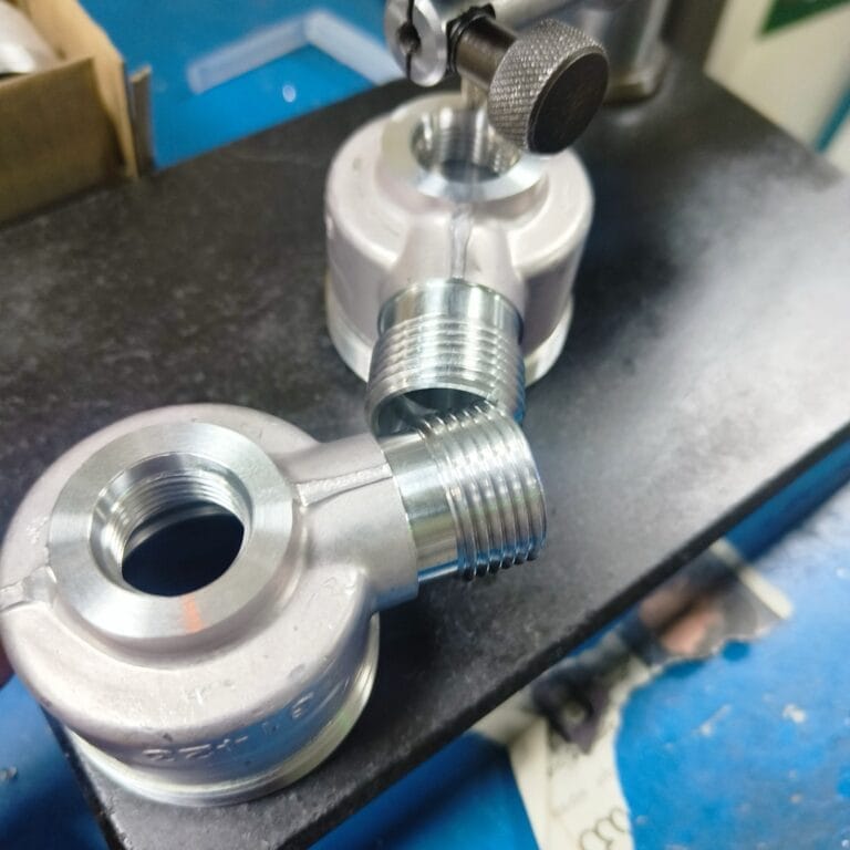
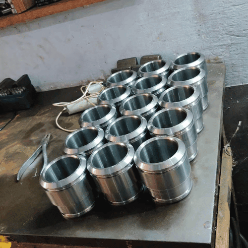
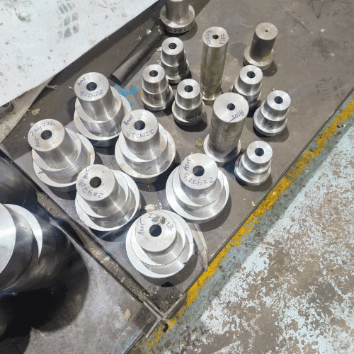
- Output Showcase
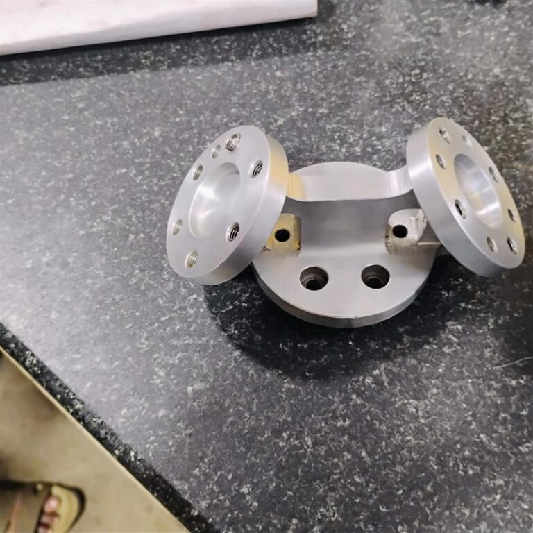
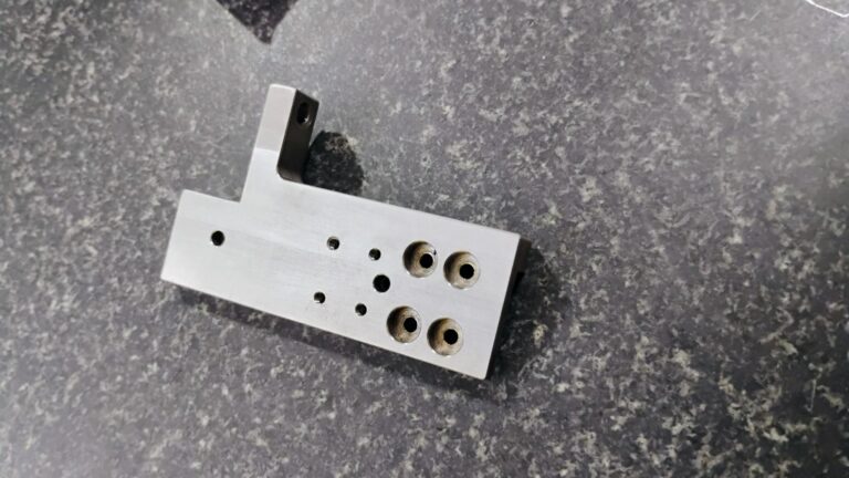
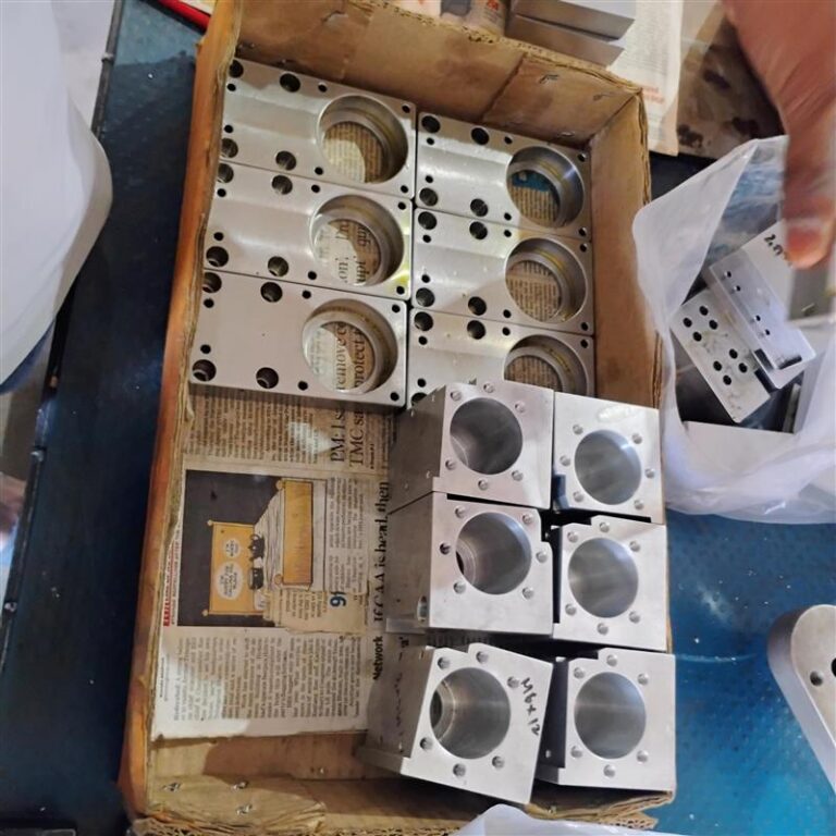
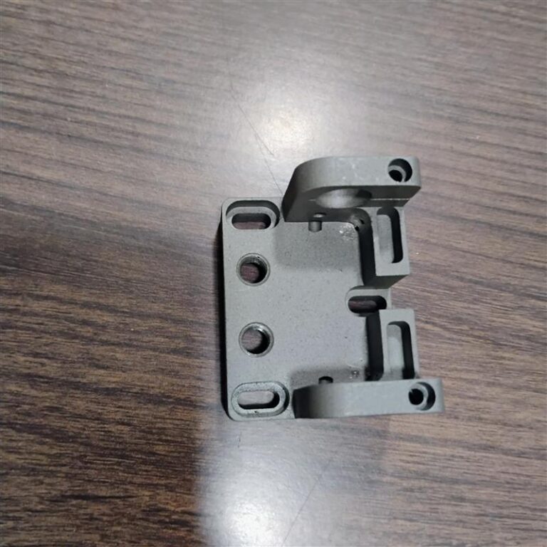
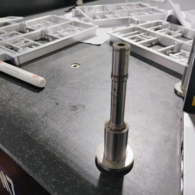
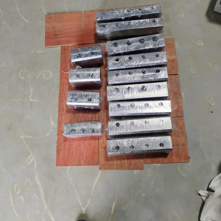
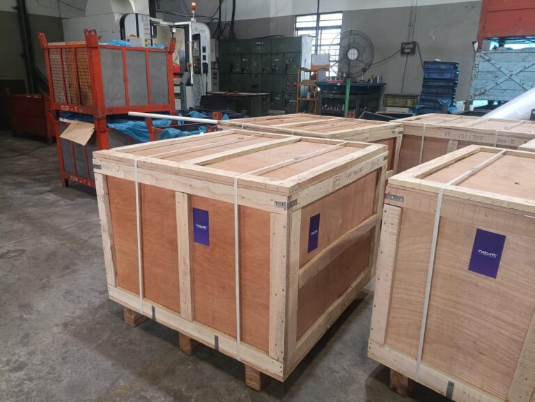
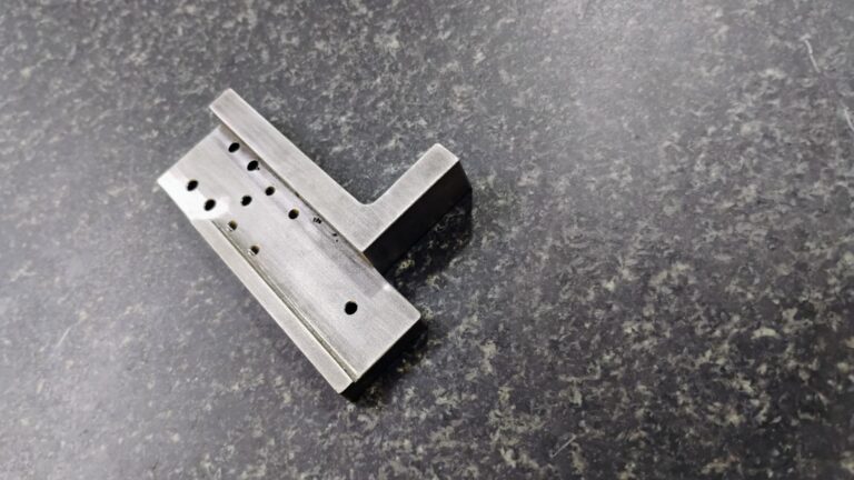
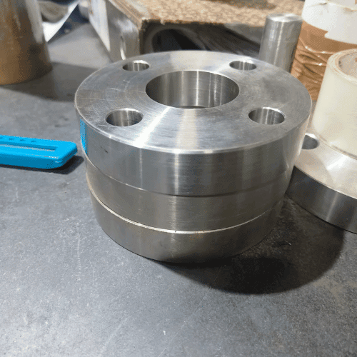
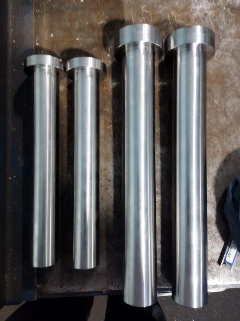
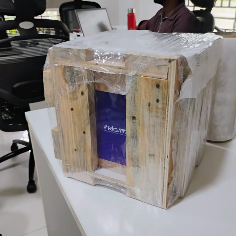
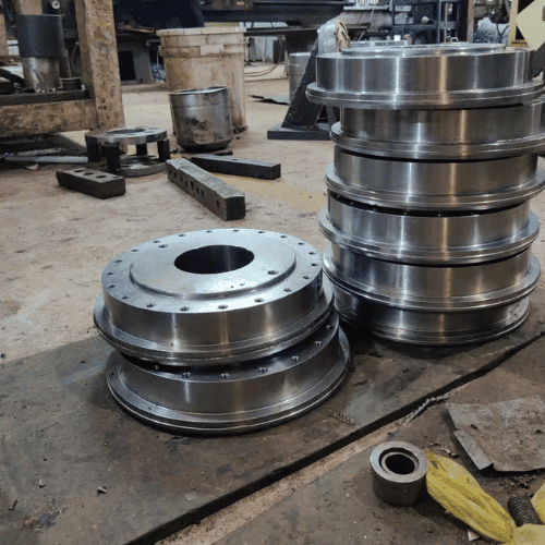
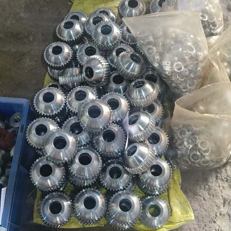
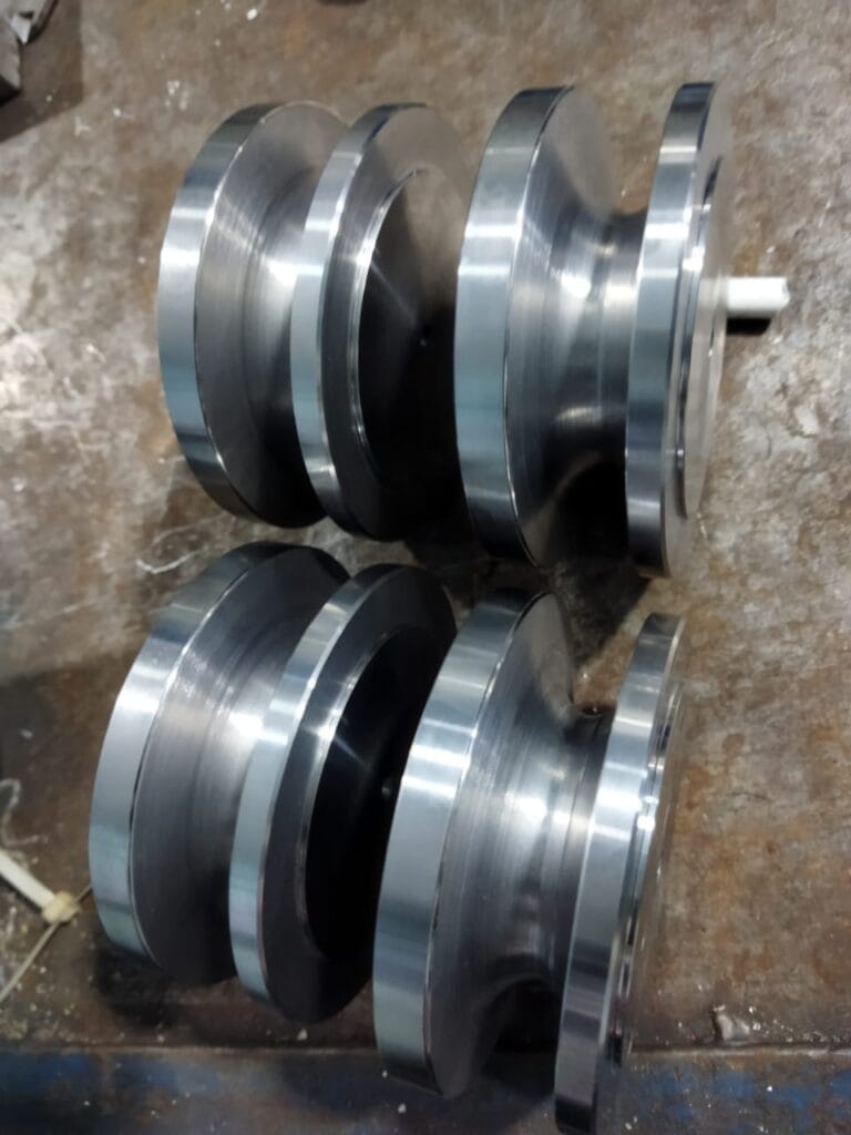
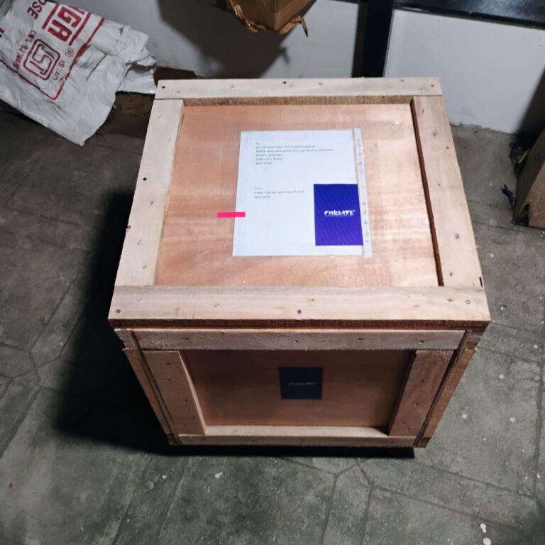
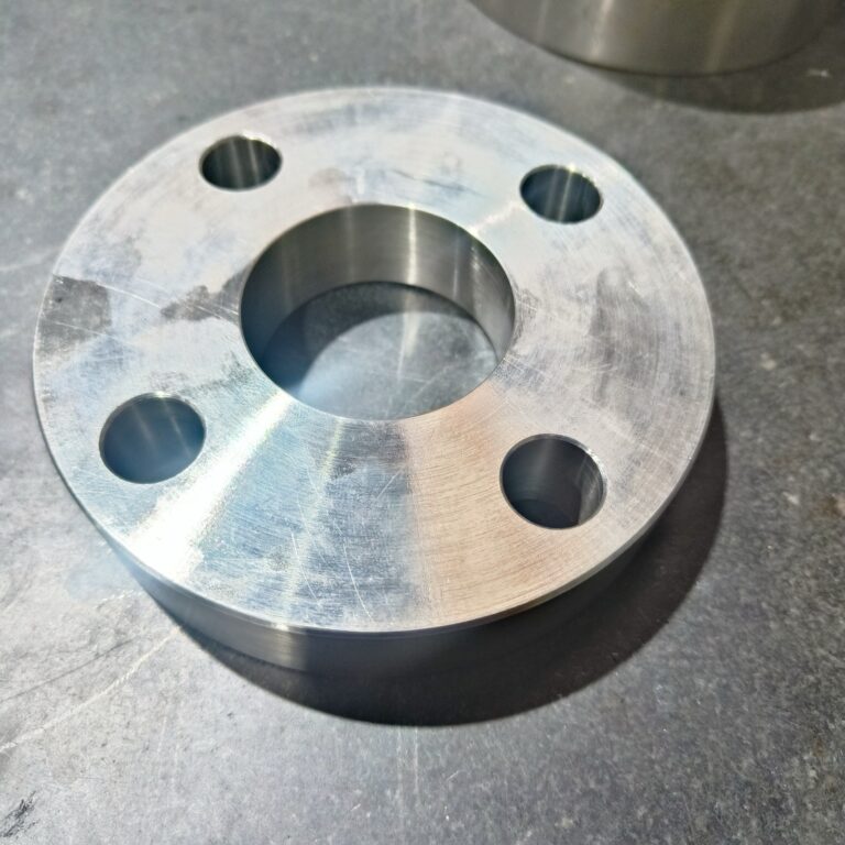
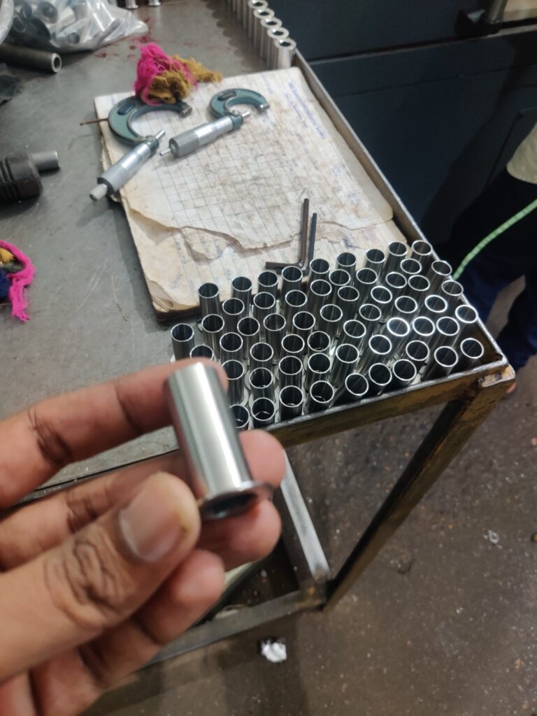
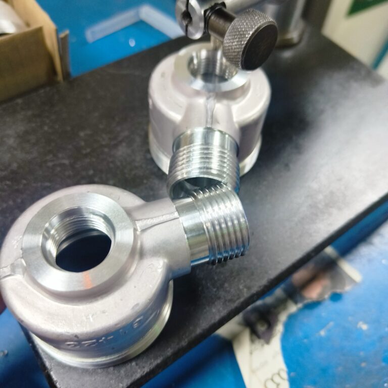
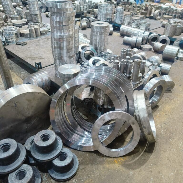
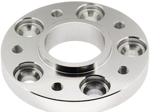
CNC Milled Parts for Testing and Proof-of-Concept Builds
We apply controlled milling setups to deliver geometry-accurate prototypes ready for lab and field evaluation. Explore parts engineered to meet real-world use cases in structural, thermal, or fitment testing.






Other Industries We Serve
We deliver machining support across sectors that require consistency, material reliability, and tight dimensional control.
- Solid Progress
Our Manufacturing Metrics
Frigate brings stability, control, and predictable performance to your sourcing operations through a structured multi-vendor system.
2.8X
Sourcing Cycle Speed
Frigate’s pre-qualified network shortens decision time between RFQ and PO placement.
94 %
On-Time Delivery Rate
Structured planning windows and logistics-linked schedules improve project-level delivery reliability.
4X
Multi-Part Consolidation
We enable part family batching across suppliers to reduce fragmentation.
22%
Quality Rejection Rate
Multi-level quality checks and fixed inspection plans lower non-conformities.
30%
Procurement Costs
Optimized supplier negotiations and bulk order strategies reduce your overall sourcing expenses.
20%
Manual Processing Time
Automation of sourcing and supplier management significantly reduces time spent on manual tasks.
Get Clarity with Our Manufacturing Insights
- FAQ
Having Doubts? Our FAQ
Check all our Frequently Asked Questions in CNC Milling
Frigate uses programmable digital offsets and toolpath mirroring to replicate part geometry across multiple runs. Custom fixturing blocks are indexed using master datum alignment to ensure zero shift during repositioning. Short-run quality loops validate critical dimensions after each cycle. High-resolution spindle encoders help maintain sub-0.01 mm tolerances even under low-volume conditions. This ensures consistent geometry in all prototypes produced across different iterations.
Frigate employs low-pressure clamping systems and radial engagement control to reduce force transfer on unsupported features. Cutter entry angles are optimized using simulation to minimize lateral push. For extremely thin sections, intermediate roughing steps are applied before finish passes. Real-time force monitoring adjusts feed rates dynamically. These strategies protect thin-walled zones from deflection or collapse during testing preparation.
Frigate uses compound zeroing routines and intermediate probing checkpoints to maintain dimensional reference across all setup stages. Indexed rotary tables allow multi-plane milling without resetting the part. CAM-driven tolerancing ensures adaptive toolpath adjustments for intersecting features. Every geometry layer is inspected using high-magnification metrology tools. This approach ensures feature alignment and integrity across complex prototype builds.
Frigate selects finishing cutters with specific corner radii designed to meet RA and RZ standards relevant to enclosure interfaces. Step-over values are calibrated per material conductivity to reduce micro-vibration marks. In-cycle feedback from spindle load variations is used to detect tool deflection and make real-time corrections. Final surface quality is verified using non-contact profilometers. This guarantees the enclosure performs reliably in EMI-sensitive testing.
Frigate retains version-controlled CNC programs linked to specific drawing revisions. Each incoming CAD update undergoes deviation mapping against prior runs using 3D comparison software. Toolpaths are adjusted only where geometry has changed, ensuring continuity in shared features. Reference datums are revalidated using tactile probe systems. This methodology supports rapid design evolution without sacrificing prototype part consistency.
We'd love to Manufacture for you!
Submit the form below and our representative will be in touch shortly.
LOCATIONS
Registered Office
10-A, First Floor, V.V Complex, Prakash Nagar, Thiruverumbur, Trichy-620013, Tamil Nadu, India.
Operations Office
9/1, Poonthottam Nagar, Ramanandha Nagar, Saravanampatti, Coimbatore-641035, Tamil Nadu, India. ㅤ
Other Locations
- Bhilai
- Chennai
- USA
- Germany
